

The FAIRINO FR10 is a 6-axis collaborative robot for tasks like palletizing, welding, machine tending, and material handling. It offers a 10 kg payload, 1400 mm reach, and repeatability of ±0.05 mm for precise handling of mid-weight parts. With a 190 mm base and ~40 kg mass, it supports flexible mounting in tight spaces. Operating below 65 dB, it comes IP54-rated (IP65 optional). Programming is via a browser-based WebAPP or optional teach pendant, with SDKs for C#, C++, Python, ROS, and ROS 2. It meets FR-series safety and product certifications for use in regulated environments.
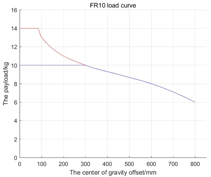
The FR10 has a 10 kg rated payload and supports up to 14 kg as an extended load, depending on the end-of-arm center of gravity. Extended loads must stay within the model’s defined load curve envelope.
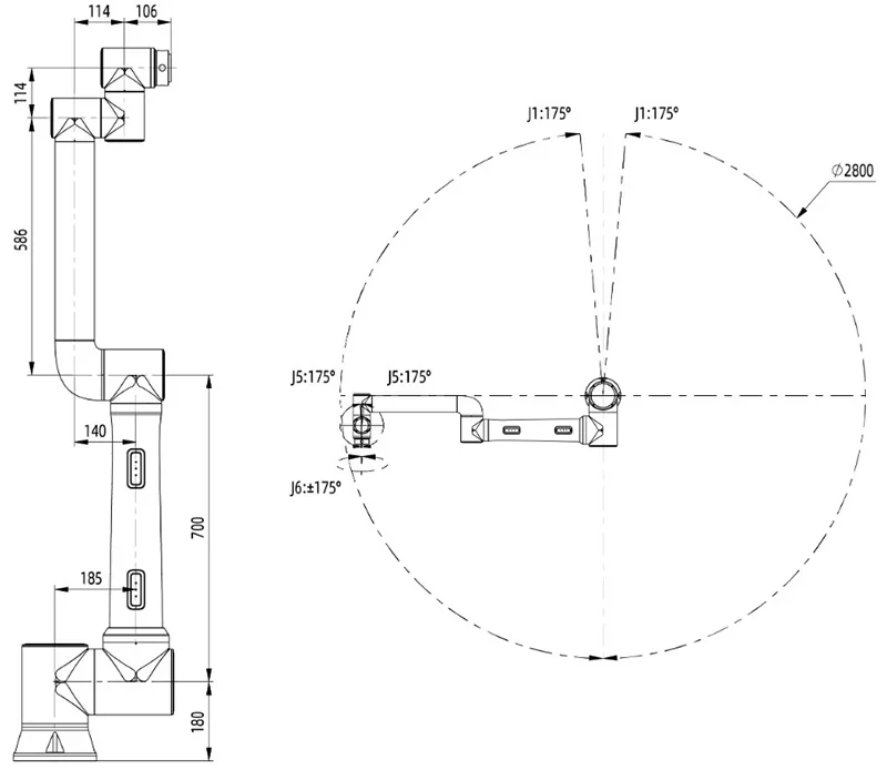
The FR10 cobot has a 1,400 mm reach, giving a 2,800 mm horizontal sweep. Joint limits are: J1 ±175°, J2 +85°/−265°, J3 ±160°, J4 +85°/−265°, J5 ±175°, J6 ±175°.
The FR10 offers ±0.05 mm repeatability (ISO 9283) for precise path and point tasks. It supports 1.5 m/s TCP speed, with joint speeds of ±120°/s (J1, J2) and ±180°/s (J3–J6). The controller enables spline PTP/LINE/CIRC motion with look-ahead planning, customizable curve fitting, and adjustable smoothing, velocity, acceleration, and jerk.
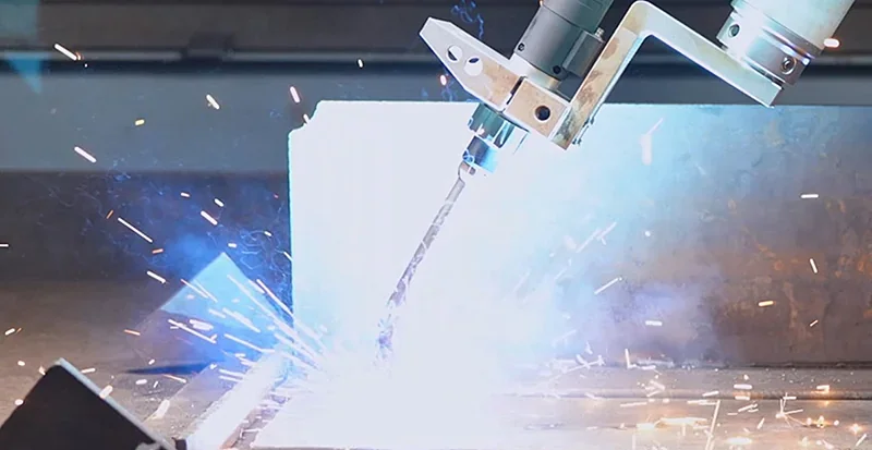
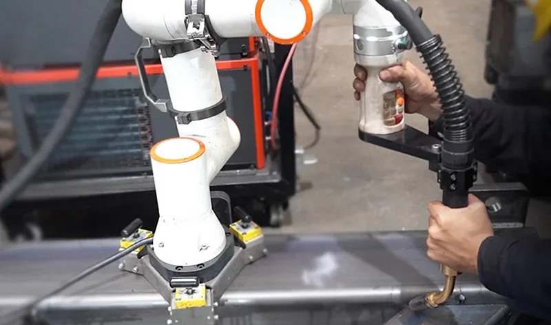
Example: Welding
Example: Assembly
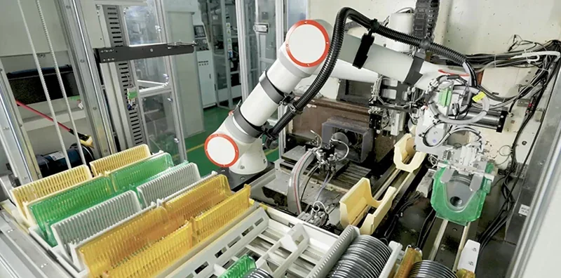
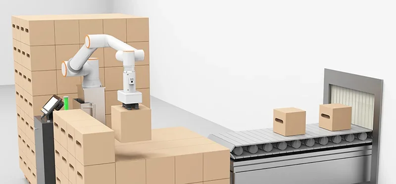
Example: Pick and Place
Example: Palletizing
Example: Spray Painting
Example: Food & Beverage Service Cells
The FR10 includes dual hardware emergency-stop and safety-stop circuits at the controller, allowing integrators to wire dedicated, safety-rated stop channels.
The FR10's end-of-arm LED indicates operating and safety states — blue (Auto), green (Manual), white-cyan (Drag), yellow (Enable), with distinct flashes for error and start/stop — enabling quick status checks in human–robot environments.
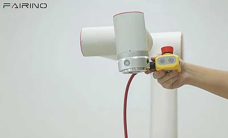
The FR10 supports hand-guiding via the end button or button box, with adjustable collision sensitivity (levels 1–10 or custom) and selectable post-contact behavior (stop or continue) to match risk assessments. Safety-rated stopping is documented, with joint-specific Category 0 stop times and angles (e.g., J1 ≈ 460 ms/0.64 rad, J2 ≈ 540 ms/0.70 rad) at full extension, max speed, and rated load, aiding collaborative-mode validation.
The FR series meets ISO 10218, ISO 13849, and ISO/TS 15066 standards, with CE and related certifications, ensuring compliance with international human-robot collaboration safety requirements.
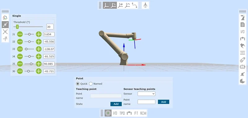
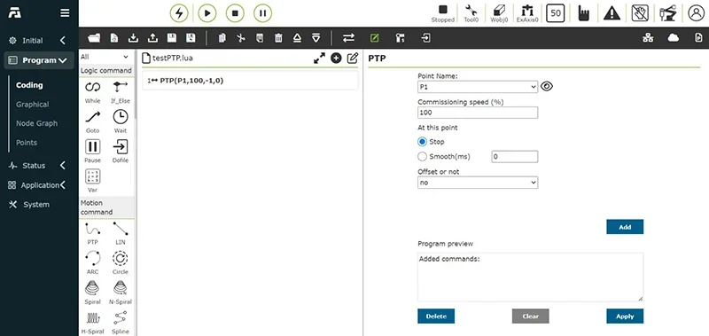
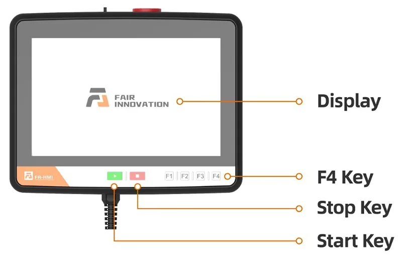
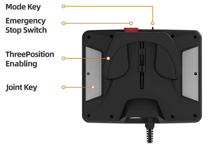
The FR10 is programmed via FAIRINO’s browser-based WebAPP on PC, tablet, or phone. The optional Teach Pendant mirrors this interface for on-arm use.
The interface supports graphical programming and Lua scripting, with UI languages in Chinese, English, French, and Japanese for local use.
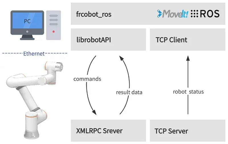
FAIRINO offers SDKs for C#, C++, Python, and supports ROS/ROS 2. The controller communicates via TCP/IP and Modbus TCP/RTU for external control and data exchange.
FAIRINO’s application kits offer no-code workflows — palletizing is set up in three guided steps, and the welding kit includes simulation to validate programs before execution.
For advanced automation, the Controller Communication Command Protocol offers granular APIs for setup and process control — covering welding, conveyor tracking, vacuum, and external axes — with commands like ARCStart(), ConveyorTrackStart(), SetSuckerCtrl(), and ExtAxisMoveJ().
The FR10 supports 50+ connectivity options. The control box includes 16 DI, 16 DO, 2 AI, 2 AO, and 2 high-speed pulse inputs. The tool flange provides 2 DI, 2 DO, 1 AI, 1 AO, and 24 V/1.5 A power for end-effectors.
The FR10 uses 24 V logic with NPN/PNP support. DOs are rated at 1 A each; inputs switch at 11–30 V. Analog channels support 0–10 V and 0–20 mA. The controller can supply 24 V/1.5 A internally or use an external 24 V (up to 2 A) source for higher loads.
Standard networking includes TCP/IP and Modbus TCP/RTU for PLC and host integration. Optional MiniPCIe cards add PROFINET, CC-Link, EtherCAT, and EtherNet/IP, configurable via the controller.
The controller supports fieldbus slave read/write for DI/DO/AI/AO and can report the active fieldbus type for easy PLC mapping. High-speed pulse inputs and RS-485 encoder interfaces enable conveyor tracking and similar applications.
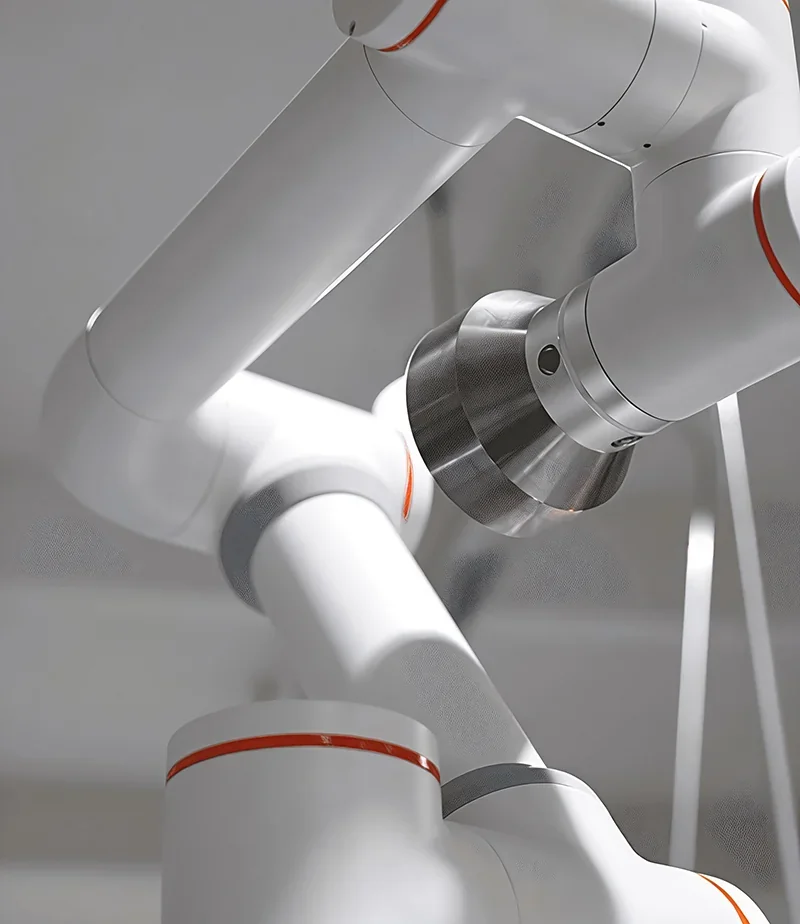
The FR10 has a durable aluminum and steel build with six rotary joints. Weighing ~40 kg and with a 190 mm base, it supports any-orientation mounting for compact cell integration.
The controller has a galvanized IP54-rated chassis, measuring 245 x 180 x 44.5 mm and weighing 2.1–2.5 kg.
The optional teach pendant is an IP54-rated ABS/PP unit, 268 x 210 x 88 mm, weighing 1.6 kg — durable and compact for industrial use.
The FR10 is IP54-rated (IP65 optional) and operates at 0–45 °C, up to 90% RH (non-condensing). It runs below 65 dB, suitable for shop floors without extra noise control.
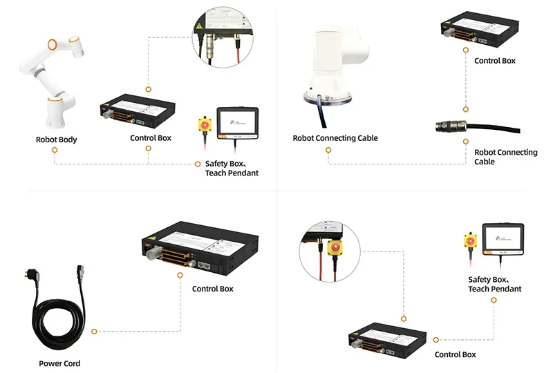
The standard FAIRINO FR10 collaborative robot arm package includes:
The FR10 ships fully assembled with a separate control and button box. After securing the base and connecting the cables and power, it’s ready to run via the WebAPP.
Please Note: Package contents are determined by the manufacturer and may change without notice. To confirm the current items included with this product, please contact a Top3DShop sales representative before placing your order.
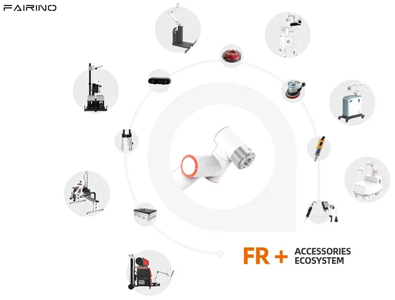
The FR10 supports 10+ accessories and turnkey kits, including operator tools (Teach Pendant, Safety Box, Explosion-Proof Cabinet), end-effectors and sensors (EPG40-050 gripper, force/torque sensor, depth camera), and four prebuilt workstations for bin-picking, welding, palletizing, and CNC operations.
| Accessory | Function | Target User | Price (USD) |
|---|---|---|---|
| Teach Pendant | 10.1″ handheld HMI for teaching via WebApp | Operators & technicians | $840+ |
| Safety Box | RJ45 PoE button box with E-stop/jog & quick WebApp access | Line operators; safety supervisors | $430+ |
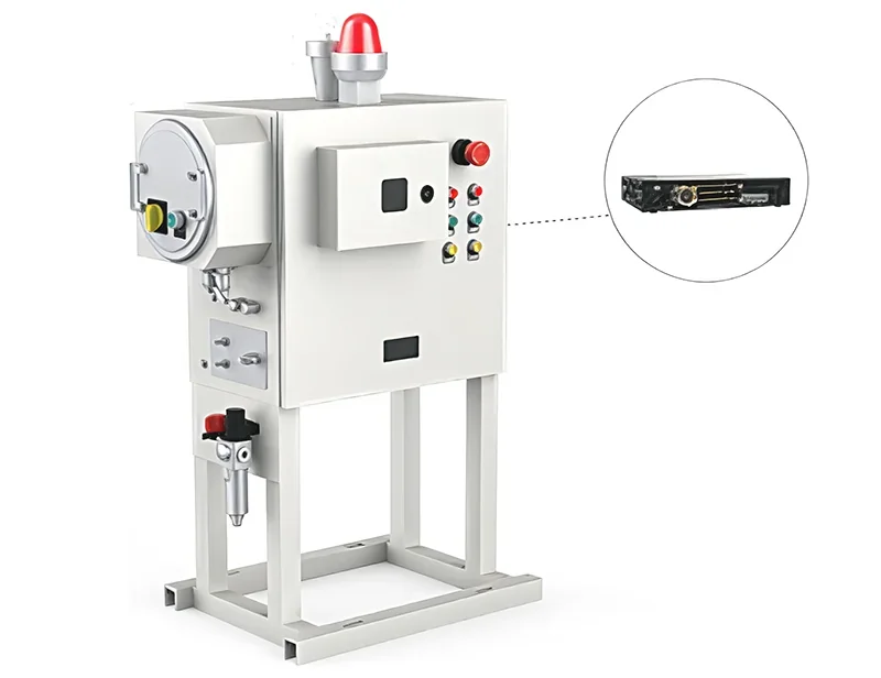
| Explosion-Proof Cabinet | Positive-pressure IP-rated controller cabinet for hazardous areas | EX/flammable-area installations | $700–$1,500+ |
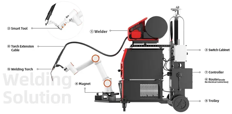
| Intelligent Welding Workstation | Mobile welding cell with 3D camera & process kit | Fabrication & job shops | $25,000+ |
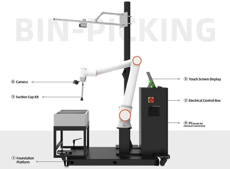
| Intelligent Bin-Picking Workstation | 3D vision bin-picking cell for mixed SKUs | E-commerce/DCs; kitting lines | $30,000+ |
| Turnkey Palletizing Workstation | Pre-engineered palletizing cell with platform, column, control box and suction kit; guided three-step setup | Manufacturing & logistics lines | $25,000+ |
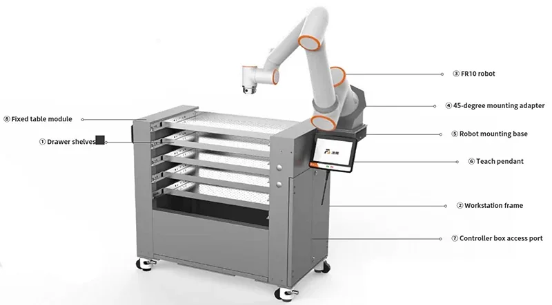
| CNC Workstation | FR10 tending bench with robot base, 45° adapter and fixed table for CNC loading/unloading | CNC shops & discrete manufacturing | $20,000+ |
The Teach Pendant is a wired handheld HMI that mirrors the WebAPP, allowing jogging, point teaching, and cell-side control. It features IP-rated hardware and a fixed cable for industrial use with the FR5.
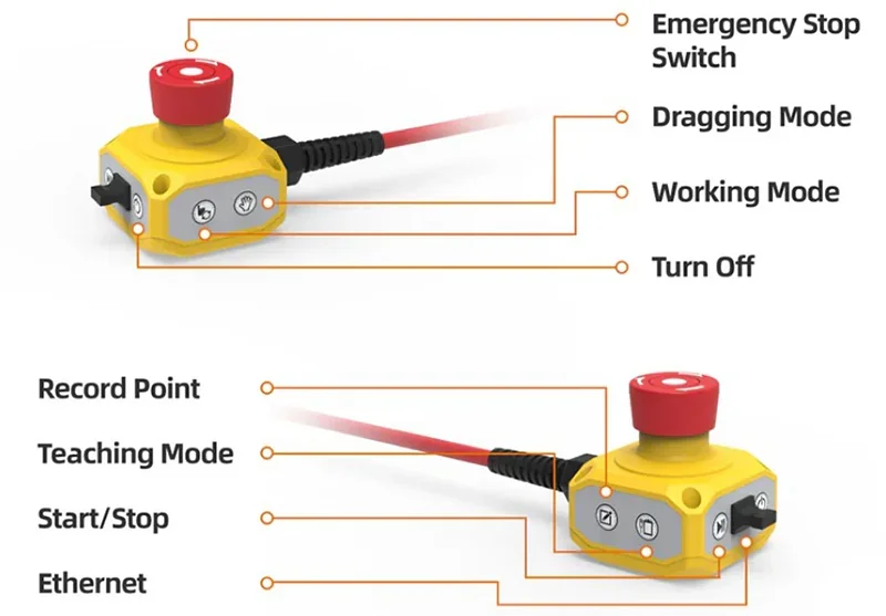
The Safety Box is a PoE RJ45 operator panel with core run/teach functions — Manual/Auto, Drag, Point Record, Start/Stop, and Shutdown — and direct WebAPP access to the FR5 over TCP/IP.
The Explosion-Proof Cabinet is a positive-pressure, IP65 enclosure for housing the FR5 controller in hazardous or dusty environments.
The Intelligent Welding Workstation is a trolley-mounted system with welder hardware, Smart Tool, controller, router, and 3D camera/software for path generation and seam tracking with the FR5.
The Intelligent Bin-Picking Workstation includes a 3D camera, suction-cup kit, IPC, and touchscreen HMI for automated mixed-SKU picking with the FR5.
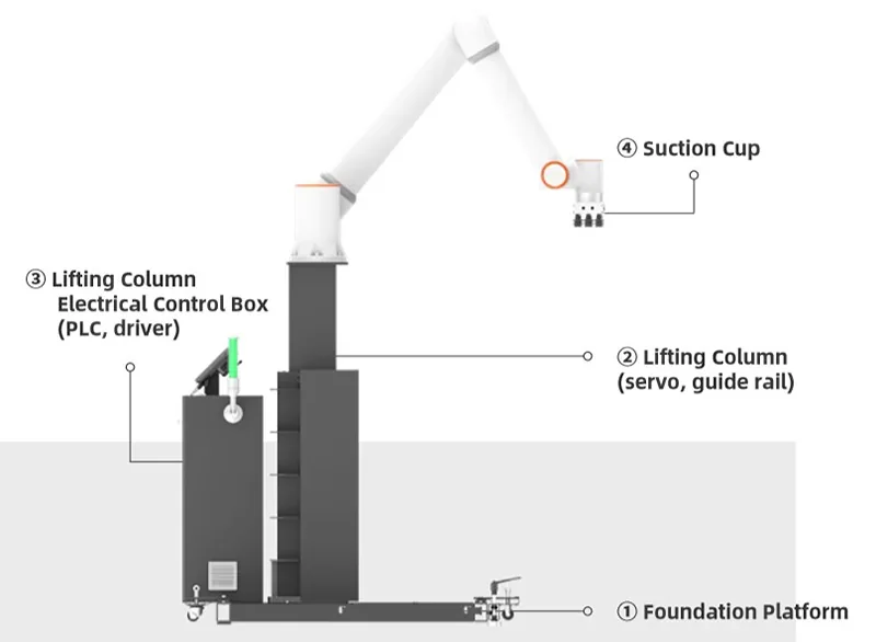
The pre-engineered FR10 palletizing cell sets up in three guided steps and includes a platform, standard or lifting column, control box, and suction cup kit.
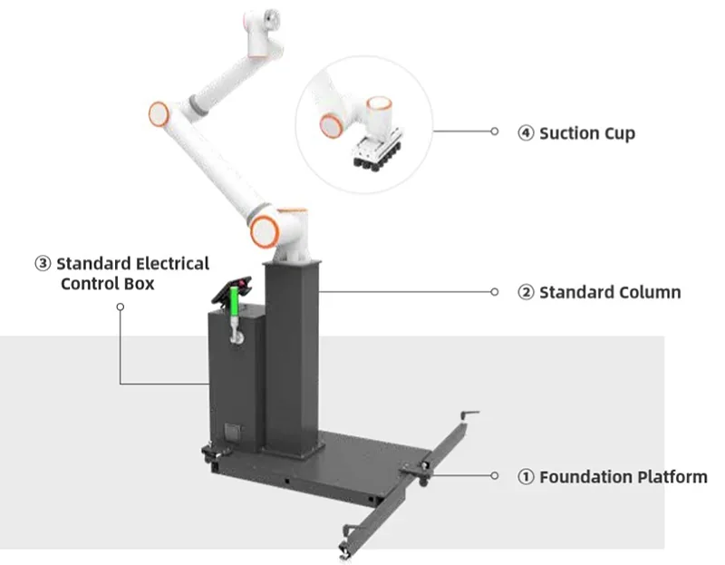
The standard column package weighs ~230 kg with the FR10 and is movable by one person. The lifting-column version extends stack height to ~2,370 mm (1140–1670 mm stroke, 45 mm/s, AC 220 V/400 W) and ships plug-and-play for fast deployment.
The compact FR10 CNC tending bench includes a rigid frame, robot base, 45° mounting adapter, and 1100 x 600 mm fixed table. Weighing ~280 kg (robot excluded), it runs on 110–220 VAC and is controlled via a web-based teach pendant for quick setup and flexible machining cell use.
End-effector ecosystem (selected FR10-compatible tools)
| Tool | Function | Target User | Price (USD) |
|---|---|---|---|
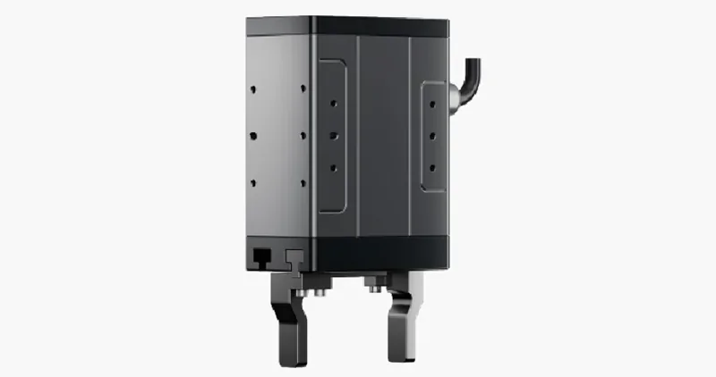
| EPG40-050 | Electric parallel gripper (0–40 mm stroke, programmable force/position) | General assembly, pick-and-place, machine tending | $500+ |
| Orbbec Gemini 2 | Active-stereo depth camera for 3D detection and guidance | Vision-guided bin-picking, localization, inspection | $250+ |
| GZCX-6F-75MM | 6-axis force/torque sensor for force control and contact tasks | Insertion, polishing, compliance testing | $850+ |
| XJC-6F-D80-H28-A | 6-axis force/torque sensor with RS-485/422 options | Advanced force applications, research, compliance control | $3,300+ |
The FR5 supports the EPG40-050 gripper via digital I/O or Modbus RTU (RS-485), enabling precise pick-and-place and tending with closed-loop position and force control.
The FR5 uses the Orbbec Gemini 2 for 3D guidance via UVC stream and official SDK, providing calibrated depth for part localization with defined working and imaging ranges.

The FR5 supports the GZCX-6F-75MM force/torque sensor via RS-485/422 for force-controlled insertion, polishing, and guarded moves, with rated loads, repeatability, and temperature compensation.
The FR5 uses the XJC-6F-D80-H28-A wrist-mounted F/T sensor via RS-485 for guarded motion and force control, with load ratings and stability suited for precision assembly and finishing.
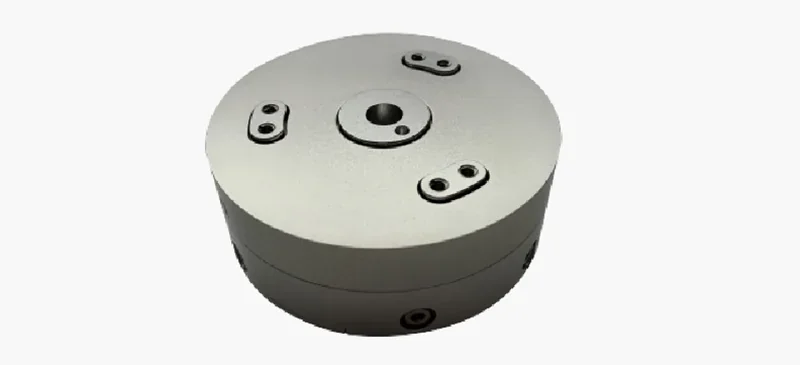
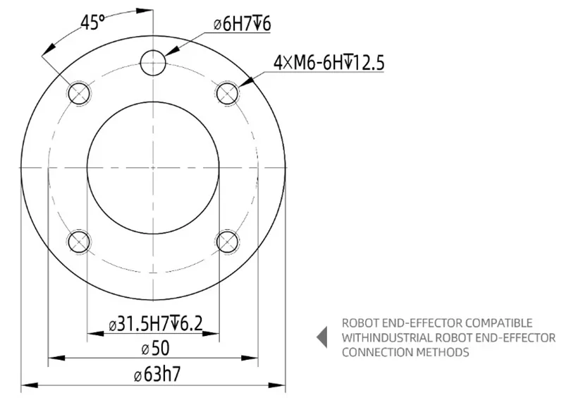
Tool interface standards and mounting: The FR10 tool flange has four M6 threaded holes (torque: 8 N·m, max bolt length: 8 mm) and Ø6 mm locating pins. The pattern is 4xM6-6H on a 50 mm PCD, with Ø31.5 H7 and Ø63 h7 pilots (see flange drawing).
The FR+ ecosystem includes vision (AL-M PND0700GB4, 0.08 mm z-repeatability @ 500 mm, 0.8 s acquisition), no-code welding kits, and turnkey bin-picking/CNC cells. Components connect via Modbus RTU, digital I/O, or USB/UVC, with the controller supporting higher-level links like Modbus TCP.
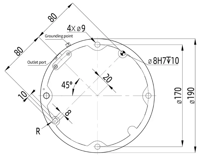
Mount the FR10 on a flat, rigid base rated for 5x its mass and 10x J1 torque. Isolate from moving equipment to prevent vibration and resonance. Use four M8 bolts (≥ class 8.8) into a stable, shock-resistant surface — at least 16 mm aluminum or 8 mm steel if using plate. Do not mount on moving devices, and ensure stable installation for safe operation.
FR10 model collaborative robot installation size
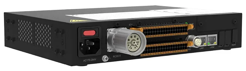
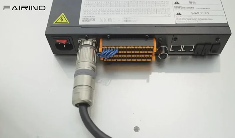
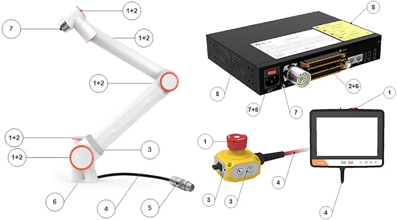
Set the control box on its feet, connect the robot umbilical to the heavy-load port, then attach the button-box cable. Connect the mains power only after both are securely in place.
Robot wiring schematic diagram
The FR10 uses either the AC MINI Controller 2 kW or DC MINI Controller 2 kW. The FAIRINO AC controller accepts 100–240 VAC, single-phase, 50–60 Hz; DC versions require 30–60 VDC — verify the nameplate before wiring. Ensure ground resistance ≤ 1 Ω and keep vents and filters clear. Wait at least one minute between power cycles.
| Maximum Input (for customers to configure the front-stage power supply) | Maximum Output (maximum output peak) | |
| DC 2kW | 30–60VDC/30A | 2000W/48VDC/41A |
| DC 5kW | 30–60VDC/40A | 5000W/48VDC/104A |
| AC narrow voltage 2kW | 176–264VAC/10A/Single Machine/50Hz | 2000W/48VDC/41A |
| AC wide voltage 2kW | 100–240VAC/10A/Single Machine/50–60Hz | 2000W/48VDC/41A |
| AC wide voltage 5kW | 100–240VAC/16A/Single Machine/50–60Hz | 5000W/48VDC/104A |
Before powering up, release the button-box E-stop. A solid green end LED means the controller is ready. For first activation, connect a PC (set to 192.168.58.xx, not .2) to the button box, go to 192.168.58.2, enter the control-box SN, then power-cycle and log in (admin / 123). Test E-stop, safety I/O, start/stop, mode switching, and confirm grounding. If the robot doesn't reach ready state, re-check umbilical, button-box, and power connections.
The FAIRINO FR10 cobot requires 10+ routine maintenance procedures to maintain safety compliance, stable motion accuracy, and reliable uptime across monthly, semi-annual, and annual intervals. These include visual/mechanical checks, safety-function tests, and control-box cleaning/verification.
Arm checklist (rear covers, screws, rubber rings, cables / cable links, base mounting bolts, and end-tool mounting bolts)
| Check item | Monthly | Semi-annually | Annually | ||
| 1 | Check joint rear cover * | V | ✓ | ||
| 2 | Check joint rear cover screws | F | ✓ | ||
| 3 | Check joint rubber ring | V | ✓ | ||
| 4 | Check robot cables | V | ✓ | ||
| 5 | Check robot cable links | V | ✓ | ||
| 6 | Check robot base mounting bolts * | F | ✓ | ||
| 7 | Check end tool mounting bolts * | F | ✓ |
Note: F = Functional check, V = Visual inspection, * = Must be checked after severe collision.
Controller / teach pendant / button-box checklist (E-stop, safety I/O, mode switching, pendant cable, control-box air filter, terminal tightness, ground resistance ≤1 Ω, and main power checks)
| Check item | Monthly | Semi-annually | Annually | ||
| 1 | Emergency stop button on test button box (teach pendant) | F | ✓ | ||
| 2 | Safety input and output functions on the test terminal strip | F | ✓ | ||
| 3 | Detection button box start/stop, mode switching function | F | ✓ | ||
| 4 | Test button box (teach pendant) cable | V | ✓ | ||
| 5 | Check and clean the air filter on the control box | V | ✓ | ||
| 6 | Check whether the terminals of the control box are firm | F | ✓ | ||
| 7 | Ground resistance of detection control box ≤1Ω | F | ✓ | ||
| 8 | Check the main power supply of the control box | F | ✓ |
Note: F = Functional check, V = Visual inspection.
Operational maintenance (shift/weekly)
During planned stops, inspect base and flange fasteners, joint covers, cables, and the button-box lead for wear or damage. Clean the arm with water, isopropyl alcohol, or 10% ethanol/naphtha — avoid compressed air to protect seals.
Preventive maintenance (monthly / semi-annual)
Monthly, test Emergency-Stop and Protective-Stop functions to ensure proper shutdown. Verify start/stop, mode-switching, and safety I/O at the terminal strip. Clean the control-box air filter, check ventilation, confirm ground resistance ≤ 1 Ω, and ensure terminals and mains feed are secure. Re-check end-tool screws, dowel pins (if used), base bolts, and external hardware — fix any issues immediately.
Comprehensive maintenance (annual)
Repeat all semi-annual checks, then inspect seals, gaskets, cable glands, and enclosures for ingress or corrosion. Verify locating pin integrity and base flatness. Document any collisions and inspect joints and covers before resuming production.
Skills and tools
Operators or line techs handle surface cleaning, visual checks, and start/stop verification. Maintenance techs perform torque checks (per spec), validate safety I/O, test E-Stop and Protective-Stop monthly, service air filters, and check ground resistance (≤ 1 Ω) with a calibrated meter. Controls techs or engineers review safety wiring and interlocks and provide sign-off. Operator tasks fit into short pauses; monthly checks need brief maintenance windows; full inspections should be done during longer outages.
The FAIRINO FR10 includes a 1-year warranty covering material and workmanship defects, excluding misuse or unauthorized changes. Claims are handled through the dealer. FAIRINO offers 24/7 support, with remote resolution in 12 hours and on-site repair within 36 hours via its Support Center (+86-400-811-0929, sales@frtech.fr). Users also have access to a documentation portal and tutorial videos covering the Teach-In/WebAPP interface.
Full warranty terms: https://fairino.com/SupportCenter
The FAIRINO FR10 is priced at $10,199.00, including the arm, control box, and button box. It's positioned as a low-TCO, scalable cobot platform. Optional add-ons include: Teach Pendant (+8–9%), Safety Box (+4–5%), and Explosion-Proof Cabinet (+27–118%, depending on spec). FAIRINO electric grippers, Gemini 2 depth cameras, and A1-01 sensors each add ~8–12%. Final pricing depends on IP rating, fieldbus options, end-effectors, vision systems, turnkey cells, training, commissioning, and local taxes. Contact Top 3D Shop for a quote.
Update your browser to view this website correctly. Update my browser now


