An average modern 3D printer has impressive functionality and can output great results. But there are times when a model isn’t printed successfully even if all preparations are seemingly done right.
We are experienced with fixing print failures, so we hope that this comprehensive troubleshooting guide can help you to identify and solve common issues. We will cover the problems that could happen to the printers using the FDM and SLA technologies, including support failure and imperfect adhesion and many others. The reason for the inclusion of the SLA issues is the rising amount of affordable desktop solutions that use this technology (thanks to new inexpensive printers).
The printer outright refuses to produce the print, no filament is extruded from a nozzle. There are many possible reasons for this problem.
Source: youtube.com
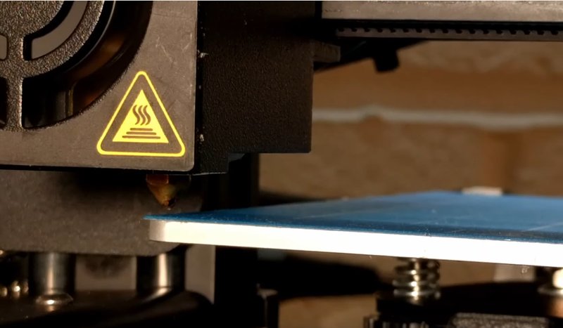
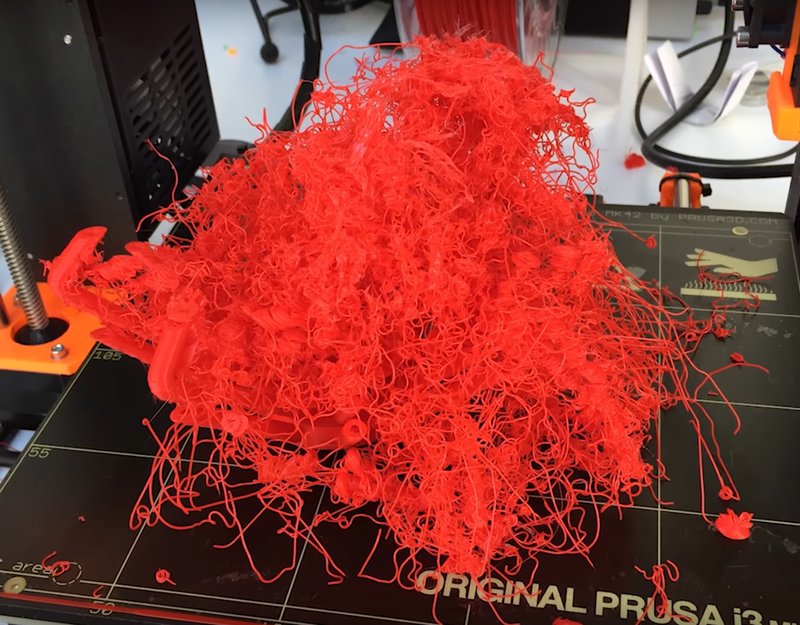
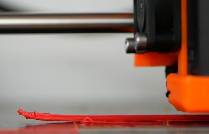
Your model has been properly set and configured, but nothing is printing. You may try to print it several times but the result is the same -- nothing happens, but sometimes the nozzle spits out a bit of filament. The other possible symptom -- extrusion stops mid-printing but the nozzle still moves.
Depending on the printer’s design the issue might be outright obvious -- such as in the PRUSA i3, where the spool is fully visible -- or not immediately seen in printers with encased or hidden reel (the Ultimaker ones are good examples).
Obviously, some printers have filament runout sensors but using third party or modded firmware might interrupt this type of feedback. And some printers just don’t have any such features.
In any case, especially if your printer’s extrusion system is of a Bowden style, you will need to extract the filament and feed in the new one.
Check for filament in the spool. Load a new one if there’s none.
Check the filament spool
Source: youtube.com
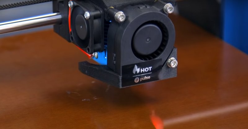
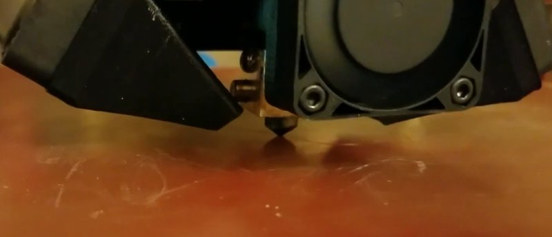
No filament deposition despite it being loaded and the print head continuing to move as usual.
Just the lack of space between the extruder and the print bed. If for one reason or another you have tuned the print bed to be a few microns from the nozzle, then the filament just can’t be extruded. And if there is, the print might end up with a lack of sticking or with the missing layers. There’s also a chance of clogging due to material accumulation.
Often the problem is easily fixable simply by slightly raising the nozzle. You can usually go to your printer’s settings and set a Z-axis offset. To raise the nozzle you will need to set the offset to the positive value. Setting in the negative one can help to manage the problem of prints not sticking to the bed.
An excessive offset might create the issue of the models not sticking to the bed.
The same result can be achieved by lowering the print bed, although not every printer has the option. But this is a more complex procedure that requires recalibration and bed leveling.
Z-Axis Offset
Lower Print Bed
Z-axis offset using Marlin firmware:
A guide that shows how to set nozzle height and level the bed in different 3D printers:
Source: youtube.com
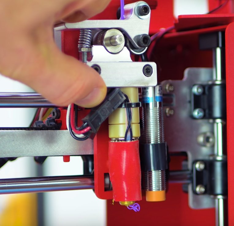
Nothing comes out of a nozzle after initiating printing. Extracting and inserting the filament doesn’t help.
A piece of filament is left in the nozzle after changing, likely due to being broken off. After loading the new one, this piece prevents it from pushing, causing blockage.
The proper and diligent maintenance of your 3D printer will drastically reduce the chance of such problems ever appearing. Even before the blockage appears during maintenance you can usually locate certain symptoms such as old filament that is already carbonized being visible inside the nozzle. It can be stuck there for a long time, only slightly affecting the quality of prints.
The symptoms are easy to overlook -- spots of filament or nicks in the walls and print quality changes. The effects are usually ignored and attributed to a variative nature of 3D printing, but sometimes the reasons are serious. Cleaning techniques such as Atomic Pull or Cold Pull can help clear it.
The stuck filament is usually noticeable when you regularly switch between various types (for example, from a PLA to Nylon). Some amount of PLA might be left in the nozzle and melted. It can cause carbonizing and burning.
A similar thing could be noticed after switching from ABS to Nylon. It usually looks like a small amount of smoke appearing for a short time after feeding new filament.
Sometimes unblocking can be simple and will not take much time. Just remove the filament, go to your device’s control panel (if possible) and find the “heat up nozzle” option (if it’s available) and increase the melting point of the filament that causes blockage. The printer can also be connected to a computer, so you can heat the nozzle using the host program. The temperature must be set to 220 °C for PLA. Use a small pin and clear the hole (but avoid burning your hands) once the material reaches this temperature. A smaller pin will be needed for a 0.4 mm nozzle.
If the nozzle is still blocked, then the filament might be pushed with another piece. Remove the filament and the feeder tube. Heat up the hot end to 220 °C if you’re reusing PLA and use another bit of new filament to push this through. If it doesn’t work, try to put extra hand pressure. But don’t do it too hard, so you can avoid bending the printer rods. Once you succeed, push it through with a needle. Then clean the leftovers with a brush.
If the nozzle is still broken (which is rare) then you will need to dismantle the hot end. If you’re not familiar with the process, it’s better to track all the steps you go through, taking notes or pictures, which will be handy for reassembling. Remove the filament and look at the manual. It will likely help you understand it should be dismantled.
Both ABS and Nylon can be used, but the latter seems to be a wiser choice thanks to a higher melting point and being better at holding its shape. But we will cover ABS in this article due to its popularity.
Remove the filament from a print head. Then remove a direct drive or the Bowden tube (depending on the system) should be removed, so you’ll be able to load the filament manually.
If you use ABS, the temperature must be set to 240 °C for ABS. For Nylon it varies and should be checked on the package. Once it reaches the temperature, leave it for five minutes without changing it or doing anything.
Push it through by slowly applying pressure until it starts to come out. Then pull the filament back and push it through again until it flows from the nozzle.
Set it to 180 °C if you’re using ABS, and to 140 °C for Nylon (but it might vary and require experimenting). Leave it for five minutes.
Pull out the filament. A carbonized material should be noticeable at the end. Repeat everything (several times if needed) until it’s clean. Slightly increase the hot end, if you’re unable to extract it.
Use a needle to clean the nozzle after heating it
Try to push the filament through using another piece after removing the feeder tube
Dismantle the hot end and try extracting the blockage
Use the Atomic Pull (Cold Pull) technique
Cleaning using a needle:
A tutorial that shows how to dismantle a hot end:
The Atomic Pull (Cold Pull) technique:
Source: youtube.com
It’s hard to miss this, at its worst the sound will make it noticeable.
By the time it usually happens, the print head will also go further the limit of one of the horizontal axis. Trying to travel beyond it, the cogs and belts will generate a lot of noise (or it will be produced by the head itself attempting to go beyond the side of the printer).
At this stage the chances of a successful print job are small. All of this is easily fixable but it’s not something you can overlook or put off for later.
The common reasons are the incorrect printer selection, problems with configuration and the issues with the endstops.
If you have a new device and didn’t have this problem before, then there’s a chance of a misconfiguration. Try to set it up again and check if you use the right firmware.
Incorrect selection of the printer in the settings is another possible cause of this problem. You can run into this problem if you try using files that are meant for one printer while using another.
Check if the needed build volume value has been set. The device will attempt to use a larger platform if that’s what the configuration shows, even if the real one is much smaller.
If the problem appears unexpectedly, we recommend confirming that everything is set correctly in the software settings. There’s a chance that a recent update has changed something. Sometimes it’s possible that the settings have been reverted to default or the newest printer model has been chosen automatically, and it doesn’t matter that you use an older one.
And the last but not least, there’s a possibility that the endstop of your printer doesn’t work anymore, if everything else is seemingly fine.
In this case, fixing the problem is going to be troublesome.
The first step for fixing this problem should always be ensuring that the correct printer is selected in the slicer software. All printers have their differences, so even if the print beds are the same in two separate printers, the other dimensions will likely vary and it should be addressed in the settings.
If your printer was recently purchased, and you run into this issue, then we recommend checking if you have the latest firmware version installed. After updating you should ensure that the settings are correct, especially those attributed to the size of the print area.
Diagnosing this problem requires more effort. Check how the print head moves. If it attempts pushing past furthest points of any axes, then there’s a chance that the endstop has disconnected. Check if it’s the case. If everything seems fine, then you should replace it with the new one.
Check the slicer software for the correct printer
Update your firmware
Check endstops
Source: youtube.com
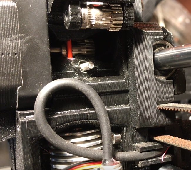
The filament spool seems full and you can notice the material in the tube, but the nozzle extrudes nothing. This more often happens with the Bowden type extruders, due to filament being hidden, which makes breakages less noticeable.
There are many possibilities, but the likeliest reason is the bad quality of your filament. Although many materials are designed to be long-lasting, storage conditions matter. For example, exposing filaments to direct sunlight for some time will make it brittle. If you feed this material into your system, no adjustments will change anything wrong.
Sometimes this might happen due to filament diameter which usually varies. There’s a possibility of the extensive tightness of the idler tensioner which will raise the chance of filament snapping under the pressure even if it’s not beyond its expiration date.
The filament should be removed. If you use the Ultimaker printers, select Maintenance and Change Material. In the vast majority of cases the material snaps off inside the tube, so it must be removed from both the hot end and the extruder. Then you can extract the material after heating your nozzle.
If you reloaded the filament, but the problem still appears, you could try using another one to check if it was the issue with the previous filament. (it might have expired)
If the newly loaded filament breaks as well, try to loosen the idler tensioner as much as possible. Then tighten it after initiating printing until it doesn’t slip anymore.
Check for blockage and clean it thoroughly.
If the issue is still present, check the temperature of the hot end and the filament flow rate. The latter should be at 1.0.
Check that the filament isn’t expired and has been stored properly
Check its diameter
Loosen idler tension
Check the hot end temperature
Confirm that the filament flow rate is 1.0, otherwise set it correctly
Source: youtube.com
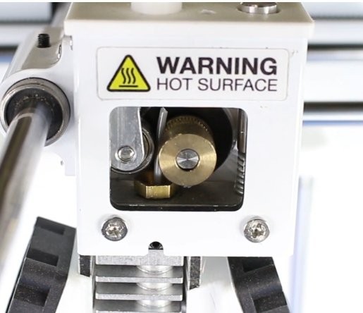
Stripping or slipping is possible at any stage of printing regardless of the material used. No filament comes out when it happens.
Common sources of this problem include the idler tension being too loose, filament blockage and the incorrect temperature of the hot end. All of these are easily fixable. The issue results in the gear of the extruder being unable to move the filament. It can’t grip and move the filament, so it slips.
If the slipping has just started to happen, the shavings and noise are usually noticeable. You can slightly apply the pressure to the filament, helping it to move. It can get the device back to working smoothly.
Loosen the tension all the way, load the filament, start printing and tightening the idler until there’s no slipping. Diameters of different filaments usually vary, but the idler is able to compensate for it. Although some other filaments may require more precise adjustments.
It’s likely your filament needs to be changed. After removing try cutting it below the slipping area and put it back. If it breaks off again, there’s a chance that it has passed the expiration date. It it snaps again and looks brittle, replace it with another one.
If the problem appeared after inserting new filament, we recommend checking that the hot end temperature is set correctly.
Help feed the system manually
Adjust the tension
Remove the filament
Check the temperature of the hot end
Everything was seemingly perfect, but the print has failed. No sticking to the bed and the extrusion ran fine. There are several reasons for this type of issues.
Source: youtube.com
Your hot end sometimes stop extruding filament for one reason or another.
In most cases the problem lies in either the nozzle or filament supply. Sometimes the reason is trivial -- for example, a filament runout. It can be just hard to notice if the filament spool is hidden. Or the idler tension is excessively tight, which might lead to the filament being stripped and not moving through your printer.
There’s also a chance of blockage.
There’s a likelihood that there’s simply not enough of filament. It might sound too simple, but there’s always a chance that we’ve forgotten to put more. Slicer programs can usually provide a material estimation for printing, and you can compare this data to your filament spool’s weight. After that you can decide if there’s enough material for finishing your print.
Stripped filament might be a reason for extrusion abruptly stopping during the process. There are different causes for that and they are covered in the dedicated part of our article.
An old carbonized filament can block the nozzle and cause several problems, including extrusion issues. This article has a part that shows how to deal with a blocked nozzle.
This problem usually happens with Bowden style systems. Broken off filament can create many issues between the hot end and hot end. Luckily, it’s really easy to identify and solve, but sometimes it’s a sign that the filament is expired. We have a dedicated troubleshooting tip on how to fix broken off filament.
Check the amount of filament
Check for stripped filament
Check the nozzle for clogging
Check for snapped off filament
Source: youtube.com
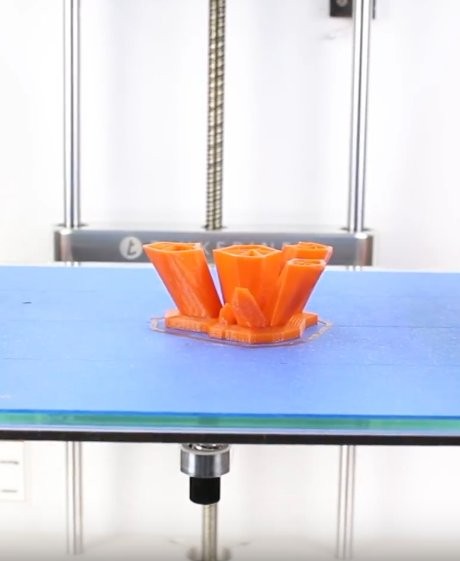
It’s common to lose your print if it doesn’t stick to the platform. Thankfully, this issue is usually easy to fix.
The bad thing is that a print can break practically at any time.
The issue not always lie within the printer, sometimes it happens due to the model having little contact with the platform -- for example, a plane that has only the wheels touching the “ground”. In this case a chance of a successful print without using adhesion, brim and supports is rather small.
Fortunately, there are many ways to fix this problem due to it being quite widespread.
More often than not, the main cause is that the print is unable to bond.There needs to be a base with a texture on your platform. This way the filament would be able to adhere. So to fix this you will need to improve the bonding properties of the surface.
An uneven print platform can cause issues as well. It means that for some parts of the print your nozzle will be too far from the bed and will have problems with a correct extrusion and first layer bonding.
Another possible issue is incorrect calibration. The space between the bed and the nozzle can become too wide, so the first layer will be dragged, which is not good.
In all of these cases you will probably see a filament spaghetti above your partially formed work or parts of the model all over your whole platform.
To increase the likelihood of the filament bonding to the print platform, you will have to add some material for a texture. Usually it means applying a layer of a stick glue that is easy to wash. You can also try a decorator tape if you use PLA. For the materials requiring a platform heated beyond 40 °C there are many different tapes available, that are better at heat resistance.
The process of bed leveling differs from printer to printer. Some use an automatic system (Lulzbots), the others guides you through steps (for example, the Ultimaker series). Take a look at your device’s manual to find out how you can probably adjust the bed.
If it’s too high, then the filament will not stick. But when the nozzle is very low, the chance that the nozzle will scrape the print will increase. Use the Z-axis offset feature in your settings and slightly adjust the nozzle. The positive value will raise the nozzle higher, the negative one -- will lower it to a close proximity to the platform.
If you’re printing on a glass or something similar, we recommend to clean it. Especially if you often use glue. The grease from your fingers and glue buildup can make the platform less sticky.
Some models can be printed without a brim. But a Build Plate Adhesion would be needed to those that are small or don’t have a significant contact area with the platform. Slicers usually provide the features called “Raft” and “Brim”.
Brim adds a layer of lines that radiate from the point of contact between the model and platform. It doesn’t use as much material as the other option, we recommend it more for various reasons. But remember that for trimming the it away, you will likely have to use a knife.
The “raft” feature is self-explanatory. It gets you a shadow of the model’s footprint made in a layer with better adhering properties. It requires more material and the surface is very rough, but the main benefit is the ability to snap off your work without issues instead of using a knife.
If there are overhangs in your model or its footprint is on a smaller side, then the support structures could help it to maintain the rigidity during printing, similar to the adhesion solutions.
Add texture
Level the bed
Adjust the height of the nozzle
Clean the platform
Add adhesion
Add supports
Nozzle height adjusting and bed leveling tutorial:
Adding and tweaking supports in Cura:
Source: youtube.com
Complex models require supports when you print them. They can be problematic to remove but they’re important for modelling.
Sometimes they fail, leaving the model unsupported.
It will be noticeable by the uneven looks of the parts, cracks appearing or the model looking overall weird.
Another issue will be the filament for supports ruining the model.
Support are complex, so your slicer software will likely present several options for these structures. The most simple way is to stick with the default settings, but this doesn’t always ensure that the model’s overhangs will be printed successfully. It’s very important to choose the correct type of the support that will keep your work steady during printing.
The support structures that are the easiest to remove are lines and zig zags. But they provide less rigidity. Grids and triangles are better for support but more troublesome to remove.
Imagine a simple bridge model with thin uprights and think about the supports. There will be a lot of work for keeping the model in place required, so if you go with zig zags or lines, then there’s a chance that the structure will move during printing and the supports will break.
But a grid structure will provide enough rigidity.
Some slicers give you the option to print the support structures without using bed adhesion. But then the small footprint of the model will have problems bonding with the print platform. enables you to print supports without platform adhesion.
If you work with tall models, then it’s likely that the supports will be excessively long, which increases the chances of it failing. In these cases we recommend to create a physical support (for example, a block) that could provide a robust support for your large overhangs.
Sometimes it’s really troublesome to remove the supports, so many people reduce their density in the options all the way. Obviously, it will cause some problems so it’s better to increase the density if the structure is supposed to be load bearing.
Filament quality is important as well -- if it’s expired, then it might not bond well between layers or the extrusion will be cracked. This increases the chances of supports breaking.
You can also check how your printer behaves when working. If it moves or produces vibrations more than usually, then there might be problems with bolts and nuts being not tight enough. After checking them, rerun the calibration.
Selecting correct supports depend on the model you’re planning to print -- large overhangs with good platform contact will be better off with zig zag or lines support. If the rigidity is more important and the model lacks bed contact, then triangles or grids will be preferable.
It’s strongly recommended to add some kind of platform adhesion, so there’s enough foundation for your footprint to bond to. For example, adding a brim will be useful.
Use it as the last option if everything else fails. You can increase the support density, so your structures will be much more rigid, but they will also be much more troublesome to remove.
Exceedingly tall supports have a higher chance of failing. You can create another object as a part of your print, for example a tall block, and it will provide a decent amount of rigidity without failing due to thinness.
There’s a chance of filament becoming brittle when it’s close to (or beyond) its expiration date. It will affect the quality of the support structures as well. Get a new one and see if the issue is fixed or at least improved.
If your printer moves and vibrates more than usual, it can be a source of some problems. Check the nuts and bolts of your model for tightness and calibrate it if needed.
Select the correct type of supports
Add adhesion
Increase the density of support structures
Make in-model supports
Change your filament
Check the tightness of your printer construction
A tutorial (no commentary) that shows how to increase support density in Simplify3D:
Everything has finished with success, but the print is visually uninspiring. In this article, we cover the list of possible issues that might cause this.
Source: youtube.com
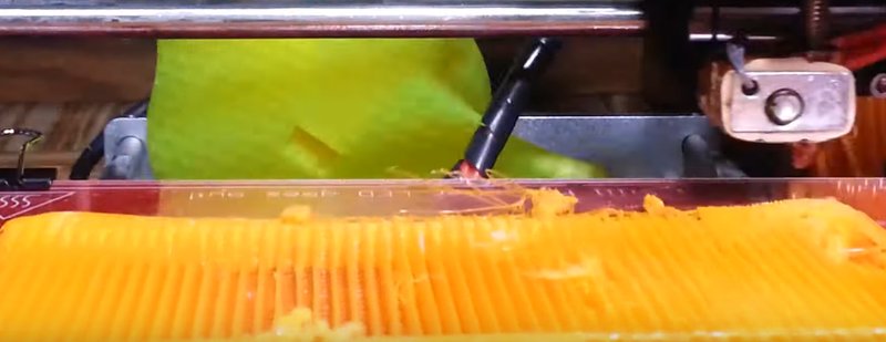
There are many different problems that can happen during printing base layers. Sometimes the result doesn’t stick (we already covered the issue in this article) or there are unplanned lines that change the look of the bottom part. The small details of the print can also be blurred into a mess.
These issues are the usual signs of improper bed level. The lack of sticking in base levels and the lines you didn’t expect can be caused by the nozzle being too far from the bed. On the other hand, blobs can appear if there’s little space between the bed and the nozzle.
Blurred mess where the fine details should be located might be caused by the the excessively high bed temperature.
There are different approaches to bed leveling, such as thorough built-in guides utilized in the Ultimaker series, and the automatic system in the Lulzbots printers.
Try to slightly lower it (by 5 degrees) and continue doing so in the intervals this small until the adhesion is perfect and no fine details are lost.
Level the bed
Lower the temperature of the bed
Source: youtube.com
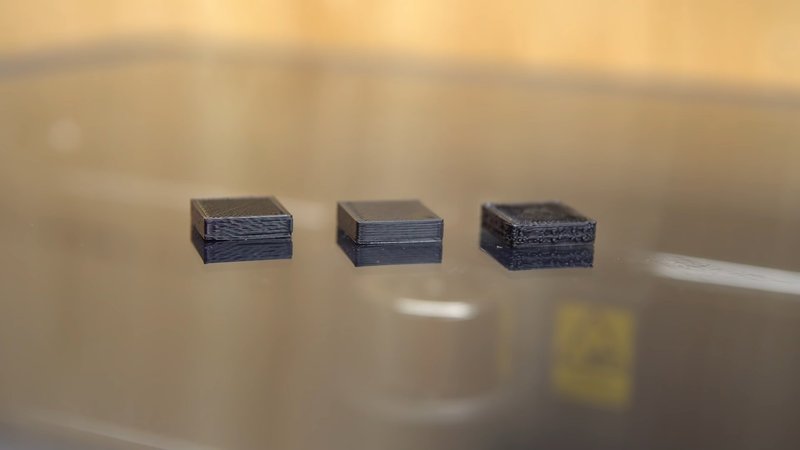
The effect called “elephant foot” is when the base bulges outwards (or being slightly larger than planned)
This issue usually happens when the model presses down on the lower side before it solidifies. It often happens when the bed is heated.
To prevent this defect, the first layers need to be properly cooled. This way they can support the structure above. But the excess cooling can increase the chance of warping these first layers. It can be difficult to achieve the balance needed. First, try lowering the bed temperature by 5 degrees. Continue experimenting with it within 20 degrees below or above the recommended one. If your Bottom or Top Thickness is set to 0.6 mm, then start the fans at a lower height.
Proper bed leveling is very important. Your platform not being level can be a source of the majority of printing issues. Printers have different ways to adjust it. You can calibrate the level according to the guidelines of your printer’s manufacturer.
We recommend making a calibration cube and checking the way the filament is laid on the bed. The cube will show how the layers are placed, so you will get a better understanding of the problems with your bed level.
You will also see if the nozzle is too close (and scrapes the material) or too high (resulting in blobs and buildups).
Often the issue might be fixed by placing the nozzle slightly higher. Avoid placing it too high, because it might cause issues with sticking to the platform.
Chamfering is also a way to fix this problem. If are able to do so, we recommend trying a 5 mm and 45º chamfer first, but you can experiment to get the perfect print.
Balance the cooling and bed temperature.
Level the bed
Raise the nozzle if needed
Chamfer the base
Nozzle height and bed level:
Source: youtube.com
The print bends (warps) upwards at the base until it doesn’t level with the bed. This might also create cracks in the upper layers and unstick your work from the bed.
Warping is not a rare issue due to occuring to natural properties of the plastic. Both PLA and ABS filaments slightly contract when they cool. The bending happens when the cooling happens very quickly.
The heated platform can be the simplest solution. Use it and select the temperature that is just a bit below of your material’s melting point -- at the “glass transition temperature”. Setting this correctly allows the base layer to stay flat. The platform temperature can you usually be manipulated in your slicer program. The recommended temperature for the material can often be found on the packaging or the spool.
If the edges of your print still bend upwards, evenly add a bit of stick glue to the bed to improve adhesion.
You can try using a bed with better adhesive properties. There are different solutions on the market. For example, a Polyetherimide (PEI), that is used by Lulzbot. It has an impressive adhesion without needing a glue. A special tape with a texture is offered by XYZPrinting. This sheet of tape can improve your adhesion if you use a platform without heating. There also exists a perforated print bed solution, offered by Zortrax. It solves the problem completely due to the models perfectly welding to the surface.
Platform calibration can also lead to this problem. Do it again, so the nozzle height will be where it should and the bed will be properly level.
You can try increasing the area where your model touches the platform. It can be a simple way to fix this problem, and the majority of slicing programs have an option to add rafts.
If the problem persists, check the advanced print settings both on the device and in the program. Increase the print bed temperature by 5 degrees increments.
Open your slicer program and look at the cooling settings. Often the fans are supposed to start working at their highest speed at the 0.5 mm height by default. You can extend it to 0.75 mm, so the base will have enough time to cool itself.
Regular bed leveling and using a glue are common recommendations (even if your bed is heated).
Use a heated print bed
Add adhesion
Try a different bed type
Level the platform
Increase contact by adding rafts
Adjust advanced temperature settings and cooling
Warping troubleshooting tutorial:
Video tutorial covering adding brims and rafts in Cura:
Source: youtube.com
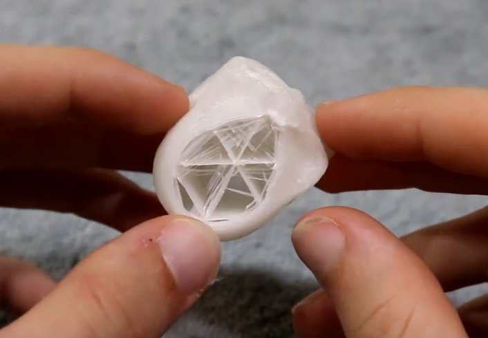
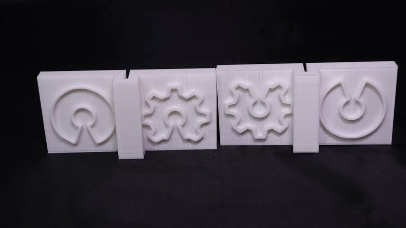
The internal side of your print is incomplete, broken or messy.
Incorrect printing of the internal side can be caused by several things. Usually, the reason is the incorrect settings, but a slight nozzle clogging can be a source of the problem too.
Go to the slicer that you’re using and find the ‘infill density’ setting. The value is usually close to 20%, if it’s less than it might cause issues. It’s acceptable to have a higher value if the bigger prints are what you’re after. If the value is not high enough, that there might be a lack of support.
The infill printing speed is important and directly affects the quality. If your internal structure looks weak, then we recommend lowering the speed.
The majority of slicers have an option to change the structure pattern. There are various of those available: rectilinear, wiggle, honeycomb and others. Try to select another option.
If the nozzle is slightly blocking, then it might affect the internal structure without affecting the exterior print. The reason of this is that the internal side needs more filament flow.
Check the fill density and change if needed
Lower the infill speed
Try a different pattern
Check if your nozzle is blocked
A tutorial covering the basics of infill patterns in Simplify3D:
Source: youtube.com
There’s a small gap between the inner structure and outer walls.
This problem used to be very common, but with the improvements of an average printing accuracy and extending the material supports, the issue is rather rare now.
But some of the newer materials can be a bit problematic (more than ABS and PLA).
The cause of gaps often lies in the lack of bonding between the infill filament and walls. Resolving this is easy.
If the value of the ‘infill overlap’ setting is a zero or even isn’t set at all, then the problem will likely appear. It’s probably the most obvious reason. It means that the software sends the information to the printer, that prevents the parts to meet.
The printing order could be a reason. If the walls of the perimeter are the first to be made, then there could be little to no overlap, so it might produce this issue.
It’s the most common reason and is usually easy to resolve. Open the slicer, find the ‘Infill Overlap’ option and set the value higher.
Cura -- the default is 15%. Try to increase it to 30%.
Simplify3D -- go to ‘Edit Process Settings > Infill > Outline Overlap’. Raise the value. This setting is basically a percentage of the extrusion width. If you adjust it, don’t go above 50%, otherwise there will be an overlap noticeable in the outer perimeter.
If the outer wall is rather thin, then there’s a chance that the infill will show through. In this case, change the order of printing, so the infill will be done first. If the slicer of your choice is Cura, untick the ‘infill prints after perimeters’ setting.
Materials like XT-CF20 are more prone to spreading due to their properties. If you use these, try to set the hot end temperature higher by 5-10 degrees. It can sometimes make a lot of difference.
There are many issues that are generated by higher printing speeds, especially if your device is not properly calibrated. So decreasing the speed is the way to go. If you still want to get your print without waiting too much, you can try lowering the top layer printing speed, this should be enough to avoid gaps.
Check the overlap
Try to print the infill before the perimeter walls
Raise the hot end temperature
Lower the speed of printing
One of the way to fix this:
Source: youtube.com
The result looks overall good, but you can see the outline of the infill through the walls from the outside.
Ghosting happens when the enfill encroaches into the perimeter. It’s especially noticeable if the walls are thin. It happens due to the internal structure creating an overlap with the perimeter while it’s printing. It’s important in 3D printing, because it helps the infill to bond to the walls. But it’s easy to solve.
An incorrect wall thickness compared to the nozzle size in your settings might be another issue. Ideally, the wall thickness should always be divisible by the nozzle diameter with no remainder.
Check if the value of your wall thickness can be divided by the diameter of your nozzle without remainder. (for example, 0.8 compared to the 0.4mm nozzle size).
It’s one of the simplest ways to deal with the problem. Try to raise the wall thickness in the software. For example, double it. This might be enough to cover all overlaps.
You can choose the option to print the infill after the perimeters in your slicer.
Cura -- go to ‘Expert Settings’ and tick the box ‘Infill prints after perimeters’
Simplify3D -- Go to ‘Edit Process Settings’, choose the ‘Layer’ - > ‘Layer Settings’ and select ‘Outside-in’ next to the ‘Outline Direction’ option.
Look if one side of the platform is affected more than another. This might mean the improper calibration. It’s worth trying go through it again.
In some cases, you will able to change the printing of the shells and infills to your advantage. If you don’t need a strong print, but require a good surface finish, then select the the option to printing from the Outside-in. If the strength is important, choose the ‘Inside-Out’ option and double the thickness of your walls.
If you wonder why it works this way, it’s really simple. Choosing the ‘Outside-In’ printing avoids creating the overlap (which produces ghosting) but the bond between the external and internal structures of your print won’t be strong enough.
Check the wall thickness
Increase the wall thickness
Change the printing order -- infill after perimeters
Check the platform and re-calibrate it if needed
Change the shells printing
How to deal with ghosting:
Source: youtube.com
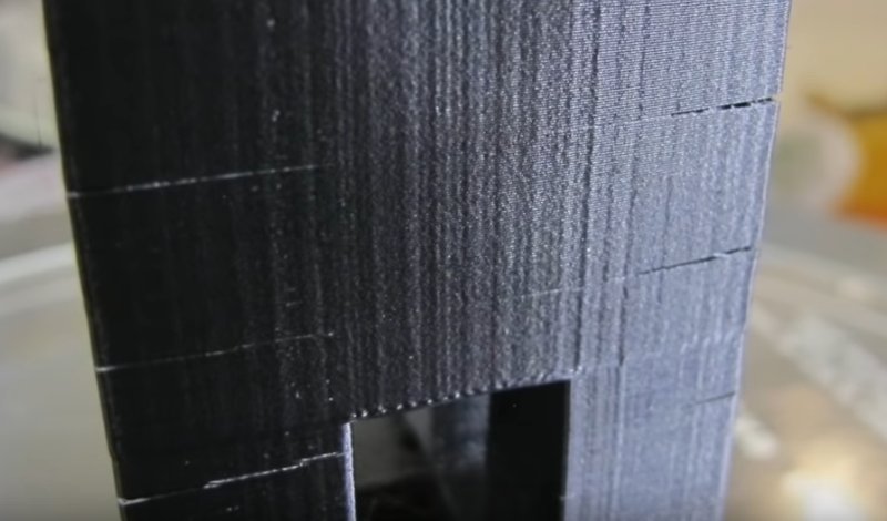
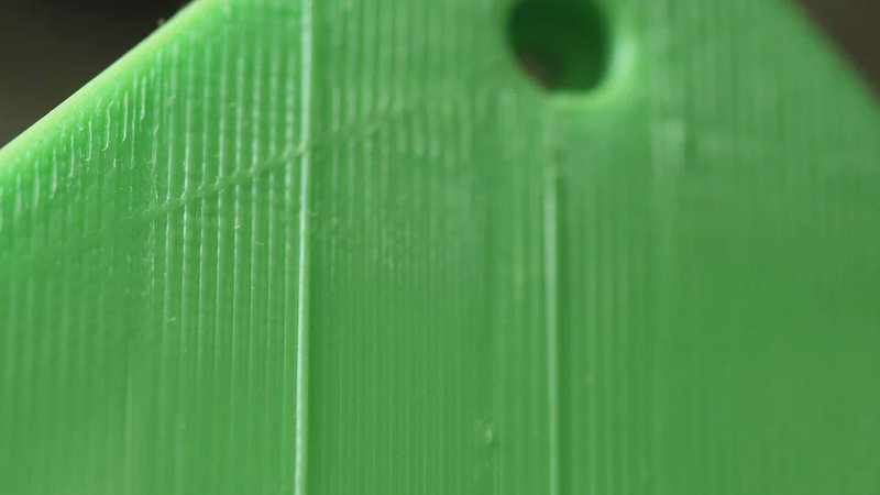
The sides of your model now have cracks. Especially if the print is tall. This issue can be really unexpected, since it usually appears in larger works and isn’t immediately noticeable.
The higher the material lays, the faster it cools. Your bed might generate heat, but it can’t reach this level, so the adhesion is worse over there.
Raise it by 10 degrees. The filament packaging usually has a recommended hot end temperature. Try to not go below or above these numbers while adjusting.
Check your fans. If they work and are directed toward your print, then reduce the speed.
Check the hot end temperature and raise it
Check the position of the fans and reduce their speed
Source: youtube.com
You can see several problems with the quality while the print is formed. If you look at it, you can notice that the layers are misaligned. The infill pattern is off too. There are misalignments on the surface of your walls. The print might be affected only in one direction.
Bolts and belts of your printer become loose over time. Misaligned layers are related to another effect -- shifting layers. So your problem might gradually develop into this more serious issue. The cause is often a loose belt.
Check all of your belts. They should be tight but not overly. If you pinch two belts together, a slight resistance should be felt. If the belt’s top section is tighter than the bottom one, then it needs adjusting and tightening. Some printers have built-in belt tensioners. You can install the 3D printed ones into the others. The manual tightening option is also possible if the others are not available.
The belts run as a single loop around a couple of pulleys. If the belt slips on one of them, it can over time get tighter at one point, and this might cause your layers to misalign.
The debris buildup can accumulate on the rods, so there will be the points of higher friction that affects the way the head moves. It might be another reason for layer misalignment and shifting. Wipe the rods and change the oil, and the problem might be solved.
If the print head movement falters at some points, it might be caused by the slight bending of the rods. Power off the device, move the print head horizontally, and if there’s any resistance, then your rods have issues. Check if they are aligned. Extract the rods, place them on a flat surface, roll and check for bending.
The threaded rods are prone to bending gradually. Run the software such as ‘Printrun’ to move the print head in the direction of the Z-axis. It will be easy to notice bending in any of those rods. Straightening a rod is close to impossible, they can be replaced. You can also install the lead screws instead of threaded rods.
The pulleys are connected to either a stepper or to the rods. Rotate one and find a grub screw. Hold the rod and the belt that is attached, and try to move the pulley applying the force to the belt. If there are no sleeps anywhere -- everything is good to go. If there is a slip, then you will have to tighten the screw.
Check your belts’ tension
Check for skipped belts
Check the rods, clean them if needed
Check for bent or misaligned rods
Check the pulleys
Source: youtube.com
The model has gaps caused by layers being completely or partially skipped.
There wasn’t enough material to make some layers causing them to be skipped. Temporary under-extrusion is when the issue is not frequent. The problems could lie within the spool, blocked nozzle or even the material itself.
There’s also a possibility that the bed was stuck for some time due to friction. The source of this problem usually lies in the vertical rods not lining up properly with the linear bearings.
Or maybe there are issues with the vertical parts of your machine. The rods dirty, covered with too much oil or just greasy can cause this issue.
Regular inspection of your printer is a useful thing to do. First, check the rods and confirm that they’re properly seated and stay in place.
Check that the rods are perfectly aligned. Disable the stepper motors or even power off the device completely and move the print head manually with a little force in the horizontal axes. If you notice the resistance, then you might have a problem.
You can notice the bearings issues by the sound. The movement being not smooth and the excessive device vibration are common symptoms as well. In this case, power off the printer, move the head horizontally and locate where your bearings are broken or worn off.
Keeping the parts of the device oiled is very important to its well-being and smooth work. We recommend a sewing machine oil because it’s common and inexpensive. Before applying, check if your machine’s rods are clean and have no grease. Wipe and clean them if needed. After that add a bit of lubrication and run some control software that will move the head. This way you can ensure that everything is evenly covered and there are not any ‘bumps’ in the way everything moves. Use a lint-free cloth to get rid of the excess oil if you’ve added too much.
Under-extrusion is another possible cause. We have a dedicated troubleshooting part covering this issue.
Do a mechanical check
Check if the rods align
Check for worn bearings
Lubricate the machine and see if everything runs smoothly
Source: youtube.com
The print starts leaning while forming. The edges are printed at the inconsistent angles. The problem might manifest itself with different severity during the printing process.
This often happens due to one of the pulleys becoming loose or one of the belts rubbing against something. Both reasons prevent the head from traveling fully and with no problems. It’s easy to fix, just check the pulleys for slipping and look at the grub screws (they should be tight and stay in place).
It is a simple fix, but sometimes the grub screws are not easily accessible. At first, you should identify which pulley causes the issue and then try to get access.
When the print leans to the left or right, then the problem is related to an X-axis. The issues in the Y-direction manifest themselves by your print leaning back to front. After figuring this out, check the belts and pulleys. Sometimes it’s easy to do so if your printer’s motors are connected to the main belt directly. In other cases (such as with the Ultimaker devices) it’s slightly more complicated.
Inspect your belts. They might be rubbing against something. Check their alignment. Even one of them being slightly angled can affect your print.
Use an Allen key. It will allow you to tighten the screw (located at the stepper motor coupler) after identifying the problematic axis.
Some devices have several pulleys, as well as belts. For example, the Ultimaker 2 has eight pulleys connected to the main horizontal rods. Tighten their screws on the axis that has problems.
Find out which axis causes the problems.
Check your belts. They should not be rubbing.
Tighten grub screw at the pulley
Check pulleys and tighten them if needed
Source: youtube.com
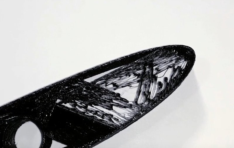
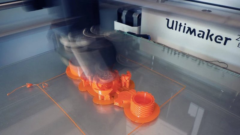
Everything seems good in a slicer. But after sending it to the printer, you notice that some parts of the models are messy while the others are printed as usual. The issues related to overhangs are considered obvious mistakes, but in reality, even experienced 3D printing enthusiasts mess this up.
FDM printing means that the print is built on a layer-by-layer basis. If there’s nothing to support the element, then the filament will end up messy due to the gravitational forces.
Ideally, the slicers should highlight this issue. But many of these programs will allow you to print without showing the lack of support structures.
Placing supports is a straightforward way to deal with the problem. Gladly, you can do so in the vast majority of slicing software.
Simplify3D: go to Edit Process Settings > Support > Generate support material; do your adjustments.
Cura: open the Basic settings and select the type of support.
Software-generate supports can be intrusive to your print and the filament may be stuck in the locations where it’s not easy to remove. Making the supports by yourself is a good way to deal with that, although you need to have some skill.
Working with extremities can prove to be problematic. Using the supports that go right from the bed isn’t the perfect solution, since they will be very long, thin and vertical, either lacking rigidity or being difficult to remove.
Design a block (avoid using a hollow one, you will need some strength), place it under the extremities of the print and then add small supports between them.
If your overhang looks like a shelf, then increase the slope of your wall by 45 degrees, so it will be able to support itself without requiring additional structures.
You can break your model apart and print its parts separately. Overhangs can be flipped, becoming the bases (in some models). The downside is that you will have to get creative and find a way to stick the parts together.
Add supports
Create in-model supports
Add a support platform
Angle your walls
Break your model apart into several prints
Overall supports guide:
<
How to make your model support free:
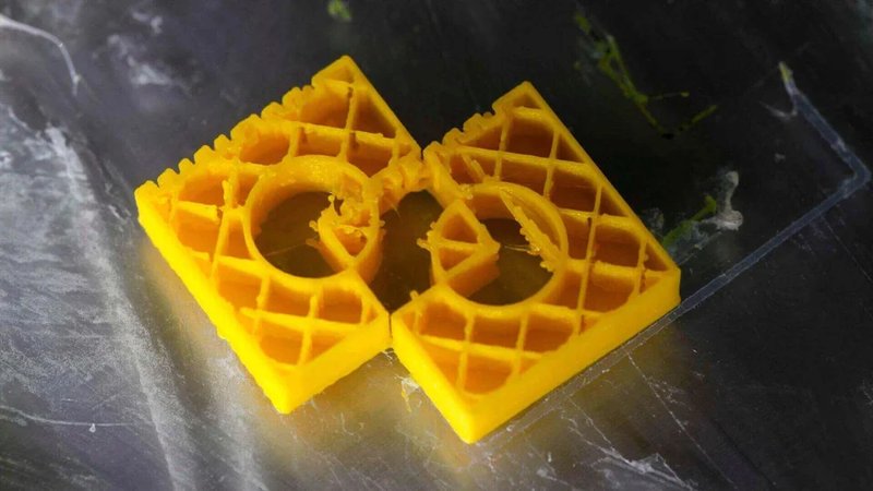
It’s rather disappointing to find yourself being unable to properly polish particular surfaces after successfully completing and printing a complicated model that includes support structures. The trouble with sanding and/or polishing off the excess material that was left after detaching supports is that it makes the model look deformed.
The matter of support structures can be approached differently at the modeling stage, but it undeniably is one of the core parts of proper 3D-modelling. However, it’s highly possible that you’ll be able to tweak your model’s design to bypass the need for support structures. For example, you can modify the model’s vertical angles or add some design integral supports. Also, make sure to unleash your printer’s potential to its fullest, as most of the devices are capable of printing 50 mm (2 in.) long bridges and 50º angles that don’t actually need any support structures.
The fastest approach to build high-quality supports is to use software applications that will automatically generate them for your model, like Simplify3D, ideaMaker, or Ultimaker Cura. Those supports will do the trick, however, they don’t tend to be neatly removable from the model. Another way is making your own support structures, but that may actually take some time as you’ll have to get some experience with the software in order to produce the finest ones.
Slicer software solutions feature a lot of options that will help you to build and manually adjust the supports in order to minimize the surface roughness after its detachment. Depending on the software, you may need to enable support structures via a checkbox. Note, however, that it’s impossible to avoid leaving any traces after the removal, since supports are an integral part of the model.
The degree of surface roughness also depends on your printing material. For example, it is increased when you work with delicate filaments like PLA, since they require more effort to finish when compared to a proper warp-resistant ABS.
Using dual extrusion printers like BCN3D Sigma R19, Raise3D Pro2 or Ultimaker S5 may cost a penny, but there is really no other way around if your products are of a complex structure that requires a lot of supports. Water-soluble filaments such as PVA will also come in handy, since they increase the decency of finished surface and make even the most complicated models easier to polish.
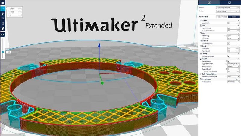
You can set your software to provide supports everywhere or just let it touch the build plate. As you can guess, auto-generated support structures are not required everywhere they can be built, so it’s better to set your supports settings to “Touching the Build Plate”. Setting it to “everywhere” will eventually result in bigger amounts of surface roughs.
Be clever with your model orientation. You can avoid using support structures by utilizing some of the perks that 3D-printers have to offer. For example, most devices are able to print fairly long bridges (up to 50 mm (2 in.)) and precisely maintain 50º angles. In order to unleash the full potential of your device, try downloading a test print or create it yourself.
In order to achieve the best surface finish and avoid unnecessary sanding, you may want to alter the support pattern in order to find out which one is the most suitable. Be sure to check all of them, especially Zig Zag.
Enter the layer view while using slicing software and take some time to analyze the supports. They are usually pretty dense by default, so you might want to change that. Reducing the density value weakens the structure but this won’t be a problem with as long as your device is calibrated properly. For example, setting support structure density to 5 while using Ultimaker Cura will be optimal in terms of final surface roughness.
Find out the recommended temperature range for the material you use and set the hotend temperature to its minimum value. Even though it lowers the layer bonding, it provides the utmost convenience when it comes to support structures detachment.
Use water-soluble filaments and dual extrusion
Relocate the structures
Unleash the capabilities of your device
Try other support patterns
Alter the thickness of support structure
Use the minimum recommended temperature
This problem manifests itself in different ways. For example, the final product may either be very fragile in contrast to good outward appearance or contain some missing segments or irregular geometry. You may also encounter some odd misprinted areas that definitely weren’t on the preview.
Basically, non-manifold geometry is caused by shapes that can only exist in the 3D-world and can’t be properly unfolded into the real world.
It is a common knowledge that two objects can’t overlap and freely enter one another in the physical world, since both of them have borders and are made of solid materials
On the contrary, the 3D-modelling world allows the object intersection. You may consider two different objects as a one united, but the trick is that the software will still recognize it as two separate entities.
The proper printing of such objects requires merging. In order for the merge to be successfully completed, you’ll have to unite the objects in one with a solitary inner cavity. Besides, make sure to remove any inner walls.
Moreover, depriving the shape of one of its surfaces will create an object with a hole. Even though the 3D-world interprets it as a figure with one less side and outlines its shape, it won’t be printed correctly.
Despite being thickly outlined in applications, the outer perimeters that touch the hole area are actually two-dimensional. The majority of easy-to-build model scenarios will be solved by the slicer software itself - the hole is very likely to get covered automatically. Be wary, however, of printing complex structures that contain such objects, since the software is highly unlikely to help in this case.
Make sure that your software is up to date, since most contemporary applications are able to automatically deal with non-manifold geometry in a timely fashion. Another bright idea would be to search for such errors manually in order to prevent any misprints.
Solution for Simplify3D: Navigate to Process settings and press ‘Advanced’. Follow this by choosing ‘Heal’ (near Non-manifold segments).
Solution for Ultimaker Cura: Click the ‘Expert Settings’ and check the box related to ‘Combine everything (Type-A)’ that’s located under ‘Fix Horrible’.
It’s really important to look at your model from different perspectives. Utilize the layer view mode provided by your software and ensure swift error correction, since controversial layers will get automatically marked by the app.
Non-manifold geometry can be neatly fixed in professional 3D-creation suites like Blender or Meshmixer. Thanks to its integrated features, the software will outline the weak points of your model and allow to fix it before the slicing process begins. This solution tends to be the most optimal.
Following the above-mentioned solution, it’s highly desirable to fix non-manifold geometry issues of the model before uploading it into the slicer software. Verify that all of the intersected and overlapped shapes are merged properly, i.e. check if the Boolean function corresponds to merge, intersect or subtract.
Update the slicing software
Adjust the advanced settings of your software
Change the view mode to check through the model
Apply different 3D-modeling software
Ensure proper merging
Your device is able to print ordinary models with ease. Without any problems, it produces one high-quality detail after another. But when it comes to printing a fine detail, the final product has a lot of misprints.
For example, there may be problems with edges and angles not being as sharp and hard as they were supposed to. On the contrary - some areas of the final product come out crooked, soft and the whole design is messed up.
Printing of fine details is usually associated with a great number of issues that can greatly decrease the quality of your final product.
In order to get the details you need, try checking the layer height first. If your printer is set to produce high layer height, it will print low-resolution details that won’t be smooth, neat and fine, even if your device is the best in terms of capacity.
Another widespread cause is incorrect nozzle size. Depending on the product you want to print, the recommended size of nozzles will usually differ by just 0.1 mm (e.g. 0.5 mm for the production environment, 0.4 mm for general purposes and 0.4 mm and smaller for fine details) , which may seem unimportant. However, there’s a very explicit connection between nozzle size and product quality.
Keep in mind that usage of small nozzles means that you’ll need to tune the 3D-printer to a more precise extent, since the overall amount of issues tends to increase when working with fine details.
Another important factor is the nozzle temperature. Before printing, make sure to remove any excess material or cloggings left in the nozzle, otherwise it won’t be able to properly extrude the material. Even the slightest blockage will lead to visible misprints and result in a crude-looking product.
Some speed adjustments are also necessary if you want to manufacture a highly detailed product. Manufacturing of fine details is carried out with slow printing speed and it’s also suggested to lower the fan speed in order to adapt to the increase in extrusion time. In the case of some devices, the optimal decision may be to set the extruder fan speed to its lowest, or even turn it off.
As a rule, fine models require the finest filaments. Even though cheap materials may look exactly like the expensive ones, they tend to be worse in terms of quality. The inconsistency of chemical composition will once again lead to warps and misprints.
Moreover, make sure to check whether the print-platform is level or not. If it’s not level, it may result in a print failure or greatly decrease the final quality of a fine model. In order to check if your device is calibrated properly, find a fine-tuned print and take some time to work on it.
Lowering the layer height provides you with increased printing resolution, resulting in properly built fine models.
Utilizing a nozzle with a smaller diameter allows printing highly detailed structures. But the smaller the nozzle the lower the tolerance, so be sure to calibrate your printer accordingly.
Ensure that there are no overhangs coming out of your printer. Remove any possible source of friction such as misaligned rods or sloppily hanged belts, since they will interfere with the printing process.
Check the nozzle condition and remove any cloggings if necessary.
The misprints are less likely to appear during a slow-paced extrusion, so be sure to lower the printing speed.
Choose the best material for your fine model. As a rule, best prints are made of high-quality filaments supplied by well-known manufacturers.
Check that the print-platform is level via a calibration procedure.
Lower the layer height
Adjust the nozzle size
Check the condition of your printer
Keep your nozzle clean
Reduce the printing speed
Fine models require the finest filament
Control print-platform level
Ringing appears as a set of visual waves on some areas of the detail surface. This problem is a minor one, and a lot of 3D-printer users seem to just ignore it. As a rule, ringing is pretty random and may suddenly appear on one printed product and disappear from the following one.
Generally, the overall appearance of the product is going to be preserved since this problem usually manifests itself as a thin wave going over the print surface. Be aware, however, that its location and harshness may change.
Even though those ringing-caused waves have a negligible visual effect and don’t really affect the final model quality, they can easily mess some prints up if the case is serious.
In general, your models may be affected by ringing due to one of two factors. In fact, the statistics show that it’s usually caused by a combination of the two.
Vibrations and speed are the two main factors that cause ringing. Vibrations are caused by a motor that’s working during the 3D-printing process. In order to minimize possible impacts of vibrations, manufacturers of 3D-printing machines optimize their devices as much as they can.
The optimization comes from the device’s weight. The more the weight, the less vibrations are going to be present. It’s impossible, however, to completely eliminate all of them. Moreover, small vibrations get passed onto the surface of furniture you’ve placed your printer on.
During the next session, take your time to take a look at the surface and check if the furniture is robust and supports your device properly while in the middle of printing.
Moreover, if you neglect printer maintenance and some of linear bearings get worn out, the vibrations will only become stronger. Don’t forget to clean your printer on a regular basis. Remove any excess materials stored inside, and be sure to oil the rails.
Before starting the machine, review the condition of the linear bearings and ensure that the print head is moving without any problems. The latter can be done by cautiously moving the head with your fingers.
Furthermore, make sure to tighten all the bolts inside the printer during a regular maintenance. If your device is home-made, these checks are extremely important.
Moving on to the speed factor, visual waves and ripples tend to appear if the printing speed is very fast. For most cases, you’ll be able to deal with ringing if you lower the speed.
If fast printing is a decisive aspect of your production and can’t be changed, try increasing the flow and extrusion temperature.
Another specific way to prevent ringing is firmware acceleration. Experienced users should be familiar with Acceleration and Jerk — these settings let you customize the speed of the head when changing directions during the manufacturing. You’ll need to modify the values depending on your printer. In most cases, these settings are set too high by default.
A good way to start is to lower the Jerk first. Follow this by lowering the Acceleration value.
Check whether your 3D-printer stands on a sturdy foundation. During the printing, take your time to see whether strong visible vibrations appear or not.
Over time, the bearings will wear out. Be sure to check if all of them are still in good condition.
Printing quality can be greatly affected even if one of the bolts isn’t tightened enough. Checking the bolts should become an important element of your maintenance routine.
Another important solution is to take care of the rods and keep them clear of dust and other pollutants. Make sure to add a drop of oil on clean rods since they require lubrication.
Try lowering the printing speed.
This one may be kind of hard for ordinary users. For your printer’s firmware, customize the values for Acceleration and Jerk and upload it back to your device.
Prevent vibrations
Check the linear bearings
Tighten the bolts
Oil the rods
Reduce the printing speed
Customized firmware acceleration
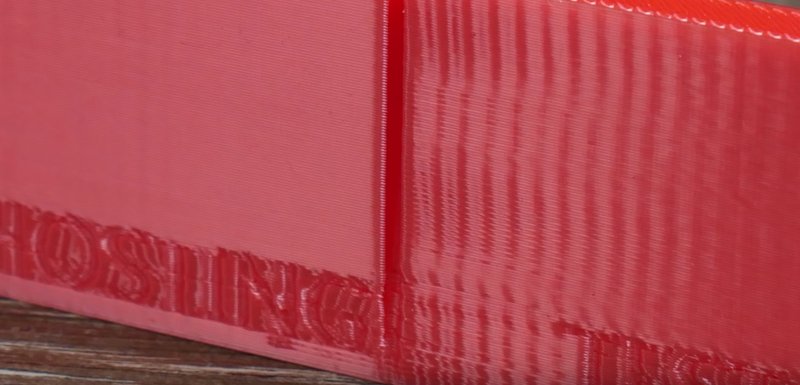
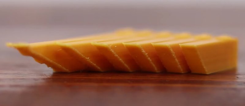
The top layer of a printed model bears diagonal scars that usually extend across the sides.
A model is printed by creating consecutive layers that are added one after another. First, the layers are applied in X-Y axes. After this, the print head follows the Z-axis, lifts and returns to the starting point to provide the next layer.
The scarring usually occurs during this stage. It can be caused by a number of reasons, including filament oozing from the nozzle. Moreover, a heated nozzle may rub the surface during rotation and leave a scar on it.
Combing is another common cause of bad-looking horizontal lines. It constrains the print head to the boundaries of printed area of the model. Any excess filament will ‘leak’ over the rest of the print and spoil the model’s appearance. Another reason is that the head is unable to be lifted as high as required. In result, heated nozzle will rub the surface and leave a diagonal scar.
Another cause for the lines is over-extrusion, though this cause is not very common. Any excess filament will leave a trace when the head lifts and moves across the surface area. If your model features long flat surfaces, you’ll be able to see a gradually fading line that consists of excess material.
Another uncommon cause is the nozzle temperature, but that will be the case only if you utilize cheap, incompatible or outdated filaments. This too will lead to a ‘leakage’ of excess filament. The latter will once again result in a trail of material because of the increased residual heat of the nozzle.
Combing is what constrains the print head and bounds it to already printed areas of your model, reducing the need for retractions. Even though the print speed gets increased, combing may cause diagonal scars to appear. Switch it off and prevent lines from appearing, but note that it will actually lower the printing speed.
If the problem still remains after removing combing, try to boost the retraction amount. No use? Time to adjust the filament flow rate and check the nozzle temperature.
Adjusting the filament flow rate will be different for different printer models. If you go with Cura and Ultimaker, be sure to check the ‘Flow details’ in the material settings (for Ultimaker 2) or navigate to ‘Custom Settings’ inside Cura (for Ultimaker 3).
If you use ideaMaker, you’ll find Open Filament Program (OFP) particularly useful for flow rate adjustment and other practical features.
First, try reducing the flow rate by 5%. Then print a calibration cube and verify that the filament is extruding properly and the issue is eliminated.
Using an outdated filament or the one that’s been exposed to some degree of humidity or affected by the sunlight may lead to shifted tolerance levels. Filament tolerance is one of the most important qualities, and this solution is unlikely to work if you utilize high-quality filaments that were stored properly. Try decreasing the hot end temperature by 5º and repeat the process, if it doesn’t fix the problem.
If the print head is unable to be lifted high enough from the model’s surface, it may result in scarring as the nozzle shifts from one layer to another and scratches the surface. Increase Z-Lift or Z-Hop in 0.25 mm increments and watch your problem being solved. If you’re a user of older devices, you’ll need to recalibrate the printer if no Z-lift or Z-hop settings can be found.
Remove combing
Increase the amount of retraction
Check the extrusion
Decrease hot end temperature
Z-Hop
Over-extrusion appears when your printer extrudes more material than required. As a result, any excess material gets stored on the printed model’s surface and causes the appearance of bad-looking strings and bendings.
As a rule, this problem is caused by Extrusion Multiplier (or Flow) value set too high. Most of the slicing software sets this value on 1 (100%) automatically, and it would be a good idea to lower it. Please refer to the previous section.
Open the slicing software and check whether the Extrusion Multiplier is appropriately set and adjust it if necessary.
Another solution is to try and decrease the Flow setting in the slicing software.
Adjust extrusion multiplier value
Adjust flow value
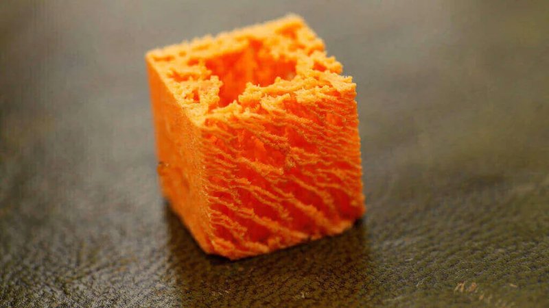
In general, this problem may be explained as an inability of the machine to supply satisfactory amounts of material to fully complete the model. It manifests itself in very thin layers and breaches. In most severe cases, some layers may be missed entirely.
Under-extrusion is mainly caused by three different reasons. The first possible reason is the filament diameter. Your slicing software may store inappropriate filament data - be sure to fix it, if necessary. The second reason is shortage of extruded material. The most likely cause of the shortage is improper software settings. Finally, the nozzle may get clogged and limit the flow access. As a result, the amount of material supplied through the extruder will be insufficient.
The most common cause for the problem is improperly adjusted filament diameter. In order to solve it, check if the diameter of utilized filament matches the value set in the slicing software. If you don’t know the exact diameter, you’ll be able to find it printed on the filament box.
If previous solution didn’t work, try measuring the filament diameter with a set of calipers. After double checking the results, set the corresponding value in the utilized software application.
The extruder nozzle may be clogged due to various reasons. Check for any remains of excess filament or dirt inside the nozzle, since it may limit the printed material access.
If previous solutions didn’t help, try checking the Extrusion Multiplier. It bears different names in different software and may also be called Flow Rate or Flow Compensation. The most optimal approach is to increase this value by five percent. If the problem still appears after the first try, increasing it for the same amount once again and continue doing it until you succeed.
Adjust the filament diameter
Check the diameter manually
Unclog the nozzle
Check the settings for Extrusion Multiplier
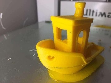
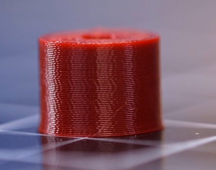
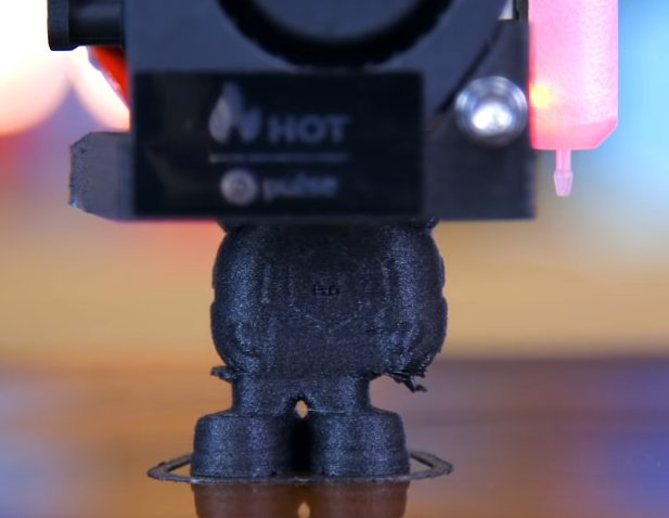
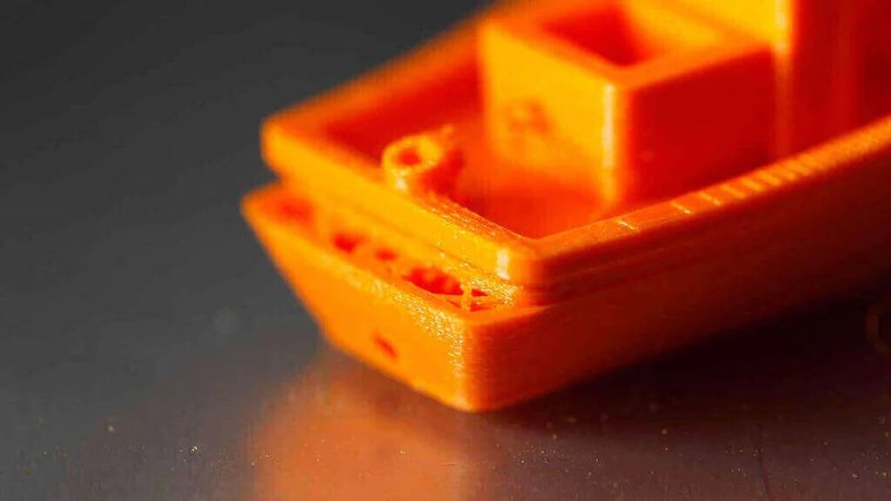
One of the characteristics of a quality filament is its resiliency to errors like hot end overheating. Therefore, it is not always easy to recognize that the hot end is too hot.
Appearance of melted, uneven layers indicates that the hot end may be overheating. As can be observed on the picture above, the issue slightly manifests on the model’s cabin and to a bigger extent on the chimney, creating a deformation that resembles melted candle wax.
Moreover, the printed model loses its efficiency if the filament is overheated due to a probable melting of 3D-printed threaded holes. If you find out that some of them are incorrect or too small, be sure to check if the filament receives enough cooling.
In most cases, fixing both of the above-mentioned problems is relatively easy. First, assure that the filament is melting just enough to flow without problems. Then, verify that the filament solidification is going smoothly and that the next layer is added on a solid surface. Another important step is to appropriately adjust the material settings for your device (throughout the filament loading process).
Be sure to double check if the material settings are set right. Various materials require different temperature conditions and it’s quite common to mix up a digit.
First, try decreasing the hot end temperature. This can be done by navigating to the settings of your printer or software. Adapt to the overheating by dropping the temperature in 41ºF (5ºC) cycles.
Accelerate the printing speed if you observe that the filament doesn’t appear to be discolored.
Check the cooling fans positioning and ensure that they are facing the hot end. If that’s not the case, try increasing the speed of the fans in order to for the filament to solidify faster.
Customize the material settings
Decrease the temperature hot end temperature in 5ºC intervals
Accelerate the printing speed
Provide sufficient cooling
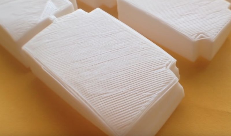
If your model’s top layer contains cracks, ugly-looking bumps, small gaps or considerable empty spaces, this subsection will help you to deal with this problem.
Pillowing is a widespread problem that generally appears due to two main causes, namely insufficient cooling and poor thickness of the top layer surface.
One of the main reasons that cause the problem to appear is improper cooling. Therefore, you should ensure that the fans are spinning and working fine. Moreover, the fans have to be able to provide the airflow to the farthest sides of the printing area in order to properly cool the layers. If the fans are working just fine, then the reason might be that they still don’t provide enough airflow. In order to fix this, explore various models (that can be printed, of course) that will alter the airflow. Another good idea would be to replace the fan or boost it.
In addition, improper cooling during the addition of another layer that, as you know, consists of molten plastic obviously brings a lot of downsides. If the material that is being applied onto inner supports isn’t cooled enough, it will fall into the gaps between support structures. To deal with this, be sure to accelerate the fans in G-Code with particular fan-controlling commands that are listed below.
In order to control the fans in G-Code, use M106, S255 and M107 commands. M106 in particular is the one to go with since it turns on the fans and lets you customize their speed. S255 accelerates the fans to the maximum, and M107 is another control command that lets you to turn the fan off.
In order to adjust the fans to ensure proper cooling of top layers, take a look at the following example. The G-Code that’ll be mentioned below was generated while working on Prusa i3 device and the utilized software was Ultimaker Cura. For example, we have a 1 cm x 1 cm (0.4 in. x 0.4 in.) cube that is going to be manufacture at the layer height value of 0.1 mm (0.04 in.), therefore consisting of 97 layers total. Then, the value of Top/Bottom Thickness is set to 0.6 mm (0.1 in.) so we trace to ;LAYER:91 and input the following code into the next line: M106 S255.
The most simple way to prevent pillowing is to upturn the thickness of the product’s top layer. Navigate to advanced settings while using your software and proceed to increasing the layer thickness by upping the value of ‘Bottom / Top Thickness setting’ to 0.6 mm (0.23 in.) if the layer height is set to 0.1 mm (0,04 in.). If you still experience the problem, increase the value to 0.8 mm (0.3 in.). The top layer thickness is a crucial setting, since at least 6 layers are required if you are printing in ordinary conditions. You may go up to 8 layers when utilizing low-diameter nozzles and smaller filaments.
Be aware that the problem has an increased probability to occur with printers that use 0.07 in. (7 mm) filament. If none of the previous solutions helped, try to utilize a 0.11 in. (2.85 mm) filament instead of the one you currently use
Ensure proper cooling
Accelerate the fan manually via G-code
Rise the thickness of your model’s top layer
Utilize a bigger filament
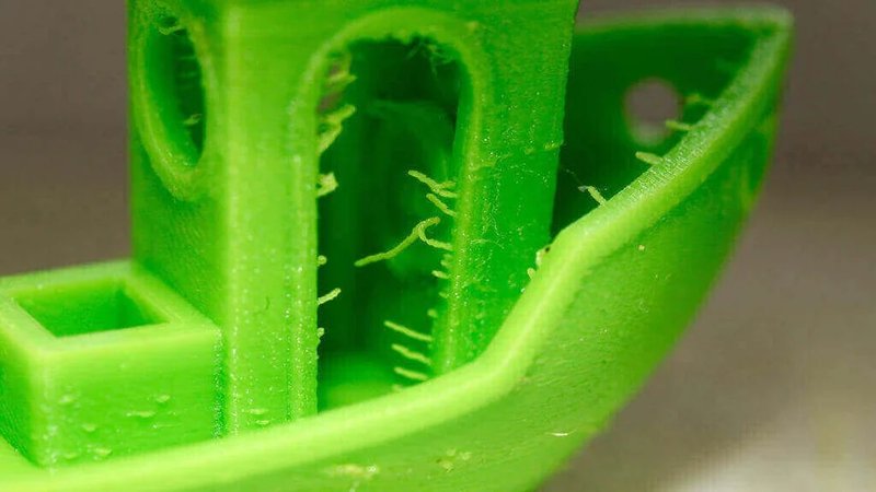
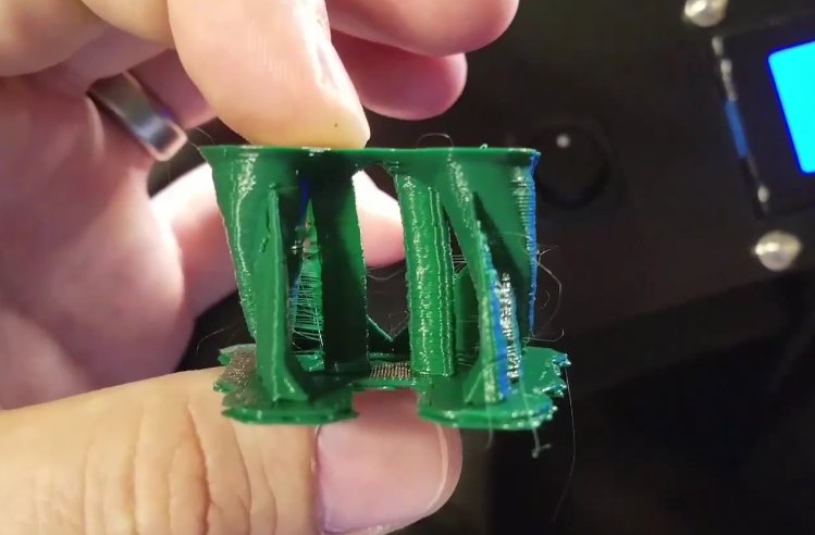
A lot of strings cover the model, making it look ‘hairy’. Your print may look like it’s covered in a web.
Essentially, this is caused by excess filament dropping from the nozzle when the head proceeds past an open area (the travel move).
As the name implies, retraction helps the filament to stay inside the nozzle by retracting it prior to moving the head. This condition is rather important in terms of quality of the final product, and can be easily activated in the majority of slicing software applications. Activating this function will prevent melted filament from dropping out of the nozzle when the head moves past an open area, therefore avoiding the appearance of thin web-like plastic strings.
As a rule, contemporary software provides an ability to enable retraction with a matter of just few clicks. This function has a pre-defined set of parameters that can be altered in order to control the printing process even more. For instance, you might want to customize minimum travel since it will most likely deal with the stringing if casual activation of retraction didn’t help.
If you enabled retraction and the problem still appears, another option would be to lower the minimum travel value in 0.5 mm (0.2 in.) cycles until the problem disappears. The value accounts for minimum travel of the print head prior to retraction itself.
The fastest and most obvious solution would be to simply remove the strings yourself. It can be done in a lot of different ways - you may use a knife, a scalpel or a heat gun.
Activate the retraction function
Decrease the minimum travel (MM) value
Clean the model yourself
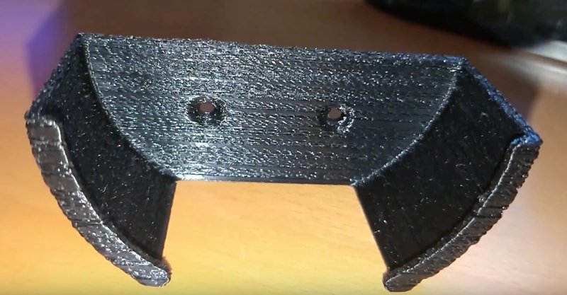
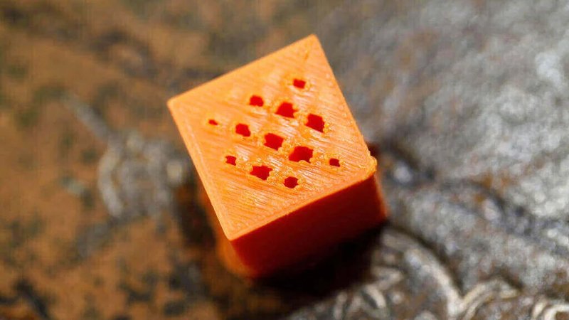
If you’re manufacturing a model that features holes, connectors or other details that need precise dimensioning, it would be a shame if even one of them came out inaccurate. This is precisely what happens if your model lost its dimensional accuracy. Some of the parts won’t align and fit and it will be hard or impossible to properly assemble the final product you’ve wanted to build.
In general, 3D-printers are considerably error-proof when it come to dimensional accuracy. Review your 3D-model once again and verify that all the dimensions are set correctly. If they are, the problem may be caused by settings of your device.
The most frequent cause of the problem is incorrect measurements. Be sure to work with such units as centimeters, millimeters or inches throughout your 3D-printing adventure. The problem will also appear if you confuse measurements when designing the 3D-model and setting slicing software i.e. mixing up the two units.
If there is no problem with units, then you should measure the parts once again. Remember - measure thrice and slice once.
If you plan to unify models that were printed separately make sure that the inserts are a little smaller than the port they need to enter.
For instance, an M5 screw won’t fit in a hole with exact 5 mm (0.2 in.) diameter unless you force it in. You should adjust the hole diameter by increasing its size by 0.1 mm (0.004 in.) for a high-quality print and approximately 0.2 mm (0.008 in.) for an average one. If your details still don’t fit and align properly, increase the hole diameter once again.
However, if some of the holes don’t look round, then the polygon count might be the case.
If you constructed a shape that’s short of polygons, it is highly possible that some of the holes bear straightened edges. Be sure to provide a fair amount of polygons in order to make the holes and connectors smooth and useful.
The same also applies to custom-built shapes that have to be joined. In case of such objects, the polygon count must be kept at a fair amount because the opposite will create round edges and cause deformation of connection points, making the details unable to fit together.
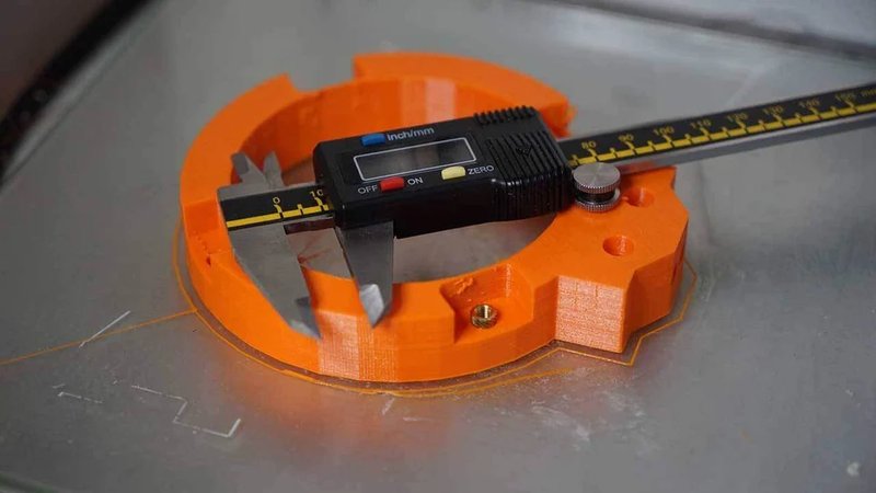
After ensuring that the problem isn’t caused by wrong model dimensions, try tuning your printer. The first step is conduct a particular research in order to see what needs to be tuned. You’ll need to manufacture a test shape of 50 mm x 50 mm (1.9685 in.) while the layer height needs to be equal to the one that will be used on the final model. Then, you’ll need to utilize calipers and verify whether the measurements are correct or not. First, check the total height of a test-cube. If it indeed is 50 mm (1.9685 in.), then the Z-axis malfunction is out of question. If the total height is different, measure the first 20 layers and see if their length is 20 mm (0.787 in.). If it is, but the total height is incorrect, then expect the problem to be caused by some of the first layers.
In order to fix this problem, examine how much the nozzle is lifted from the platform and ensure that the value corresponds to your device’s margin of error relative to the layer height. For example, if the nozzle height consists 1 mm (0.004 in.) and the setting for layer height is 2 mm (0.008 in.) the most likely cause for the problem is excess material that’s being added to the first layer of your print. Correct it by recalibrating your machine and increasing the nozzle height, or decrease the layer height.
Next, the X-Y dimensions have to be thoroughly examined. If all the proportions look correct but those dimensions are slightly smaller than they were designed to be (e.g. 1 mm/0.004 in. smaller), the problem could appear due to thermal properties of the filament. For example, filament thermal contraction is a widespread issue when working with ABS plastic. You’ll have to up the scale of the print depending on the error percentage. This problem can be prevented by using high-quality filaments.
After adjusting the process, check the holes once again. If the problem still appears and there are some layers that stick out a little, this is a sign that something might be wrong with the nozzle temperature. If the nozzle becomes overheated, it still completes the layer but may lead to dripping of slight amounts of filament which causes the issue.
If the hole was supposed to be round but is oval instead, there may be some issues with untightened belts or X-Y axes misalignments. Check that everything is finely tightened and screwed into corresponding places and try printing again.
Verify that you work with correct units such as centimeters, millimeters or inches when using your 3D-printing software.
If your product needs to be fit together with another one, manually measure all the connectors and holes with calipers once again.
In case of manufacturing a screw hole, you should first create a model of a screw with a slightly increased diameter and then use it to extract or create a boolean subtraction from the model where the gap is supposed to appear.
If the model’s polygon count is low, this can cause the model’s edges to straighten or flatten a little. Maintain a fair amount of polygons in order to provide smooth gradients and ensure that everything fits and aligns properly.
In order to check if the X, Y and Z dimensions of your model work correctly, print a calibration test cube.
If any excess material is oozing from the nozzle and it has blobs or other obstacles which block the nozzle access, try reducing the print temperature.
Be sure that there are no loose belts and all axes are straight and aligned in a proper manner.
Exclude the possibility of measurement units error
Make screw holes with a slightly larger diameter
Keep a fair amount of polygons
Level up the printer accuracy
Reduce nozzle temperature
Adjust the belt tension and rails
Even though the effect this problem may cause on the model outlook is usually quite subtle, it will be very distinctive in some of the cases, like with Benchy on the picture above.
Layer shifting is caused by a number of different reasons, some of which are relatively straightforward. For example, knocking the printer during the manufacturing process may cause the shifts. For more complicated reasons, you might want to check if the rods are all fine and aren’t bent or misaligned. Another difficult issue is that during the printing process the nozzle path may be blocked by the model, therefore resulting in a change of platform position.
Ensure that the printer is placed on appropriate surface and provide it with a reliable foundation, if necessary. Moreover, it’s restricted to knock, push and play with the printer especially during manufacturing process, since even one little push is enough to dislocate the print base and cause shifting.
A lot of contemporary devices feature print beds that can be detached to some extent. This feature is particularly useful when you want to remove the model without damaging the machine, but it also entails the possibility that screws and clips may come undone over the time. Therefore, it is of utmost importance to always reinstall the print bed properly so it will be tightly fixed to a place and immovable.
If too much cooling is provided to the model’s upper layers, they will warp and get deformed. As the deformation of top layers occurs, they rise up and may clog up your nozzle when it moves. Sometimes you won’t be able to even detach the model from the platform - be sure to utilize high-capacity stepper motors that will allow you to move the model and platform around if it comes to this. A main solution to prevent the upper layer warping is to adjust the fan speed by lowering it.
The increase of printing speed usually improves the time-efficiency, helps with filament flowing and lets you save time. However, the rest of your printer may just be unable to keep up the pace. When in the middle of 3D-printing process, try listening to your surrounding. For example, if you hear some clicks then your printer may be going too fast. Before doing anything else, be sure to verify that there is no filament slipping since it may cause the clicking too. You can easily decrease the printing speed by using slicing software applications.
If the above-mentioned solutions didn’t work, be sure to check the belts. An easy way to verify that they’re all fine and running is to check all of them in a quick succession. You should pinch the two together and check whether their tension is the same or not, and repeat it until you’ve examined all the belts. If the tension is different, adjust the positions of the belts to make it even. Stretching is another issue when it comes to rubber belts. This can be detected if you see that they slip on the belt drive pulleys. A simplest solution is to simply replace your belts with new ones. If your device is home-made, be sure not to utilize over-tight belts. The belt tensions can also be adjusted by means of belt tensioning screws feature in some devices like Prusa i3.
In general, the couplers are located in specific places since they are connected to a stepper motor and to a particular rod that controls the print head. Carefully examine one of the couplers and locate a small-scale set screw. Then, apply some force and pull the belt while holding the rod and make the pulley turn. Moreover, you should check that the coupler and stepper/rod are aligned tightly together and there is no slip. Tighten the set screw in case if they aren’t.
The rods will get dirty over the course of repeatable printing sessions. Therefore, there may be some amounts of rubbish stuck to it that restrict the free movement of the print head and facilitate the appearance of layer shifting. Clean the rods and oil them once again in order to resolve the issue.
The final solution would be to check if one of the rods may have gotten deformed. Make sure to turn your printer off and check the printed head manually, moving it in X-Y axes. If the head isn’t moving free, check for correct rods alignment. If the rods are aligned correctly, detach them and flatten over a flat surface and check for the bendings.
Secure your printer
Fixate the print bed tightly
Reduce the cooling of upper layers
Decrease the print speed
Check the condition of belts
Check the drive couplers
Maintain the rods
Check for bent rods
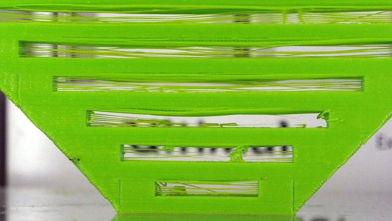
In their essence, bridges represent lines of plastic expanded over two points raised above the rest of the model. For example, if there is a 10 cm (4 in.) gap between columns with nothing below, then the structure printed above the gap is the bridge.
For the most part, filaments are very liable to bridging. If you utilize a finely tuned machine, you can be surprised with how big of a distance you can cover with bridging. But if your printer fails to cover even the smallest gaps then it’s a sign that something is wrong.
For example, your device is unable to bridge 1-3 cm (0.4-1.2 in.) gaps. This has a variety of different causes and is fairly easy to resolve. For the main reasons: lack of extrusion, filament bulges down or even flows down the gap completely, instead of hanging across.
As a rule, you can swiftly understand what exactly causes the problem when you look on the failed bridge.
Another important thing to mention is that the approach to bridging differs from one slicing application to another. For instance, Simplify3D has a special option that’s called ‘Bridge’. It provides optimal extrusion and cooling settings and the results are fairly impressive.
The most frequent cause of improper bridging is that the gap is too long. This distance depends on the material and device you utilize. If the gap is too long, the filament will bend down in the middle of the bridge or simply collapse.
Another important reason for the problem is that the filament isn’t cooled quick enough and is unable to support itself over an empty space.
Be sure to maintain optimal extrusion speed, since a fast-moving print head will definitely cause vibration that in its turn will cause instability prior to filament setting.
Another issue that can be easily identified by seeing improper bridges with filament sags is extrusion temperature that’s been set too high. If the thickness of extruded material is uneven, this must be the case.
Design or download a 3D-model with columns and bridges of different length and check the capabilities of your printer. It’s a good idea to start with 5 cm (2 in.) long bridges and then up the value by 5-10 cm (2-4 in.) each consecutive time.
The quickest solution for this issue is to simply add some support structures below the problematic place.
For this, you should boost the speed of the extrusion fan in order to provide sufficient cooling. If the filament is unable to cool quick enough it will be impossible for it to cover long distances and therefore provide proper bridging.
Haste makes waste when it comes to bridging. Ensure that the extrusion is going slow and steady, because the material needs some time to fully outline and build a bridge.
One particular application for this solution is Simplify3D. It provides you with a bridging option that automatically recognizes any segments of your model that require an increased degree of cooling and decreased extrusion speed.
Find out optimal length for bridges
Add some support structures
Provide appropriate cooling
Ensure hasteless extrusion
Use a bridging option
You completed the printing and the model looks beautiful, but there still is a problem.
Here you can find the solutions for FDM printing problems that weren’t previously touched upon in this particular article.
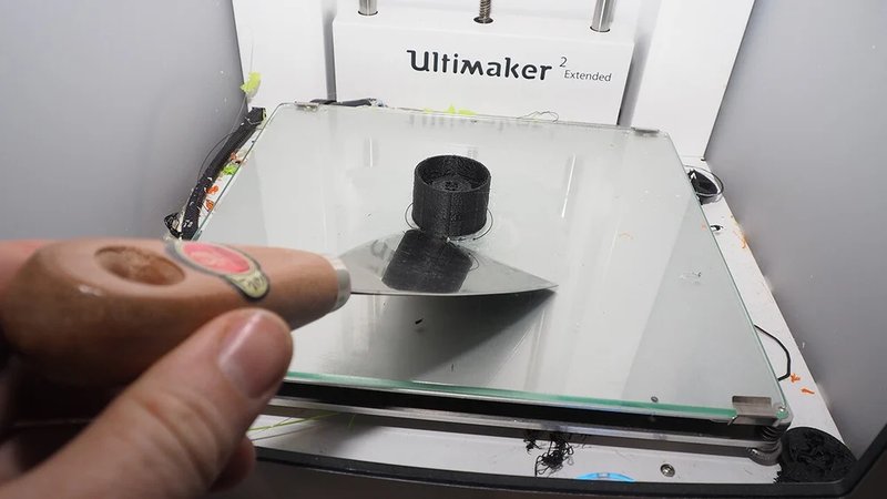
The printed models are unusually firmly welded to the platform. Another common problem that will be also furtherly reviewed in this guide is when the model won’t stick at all. But as frustrating as it may sound, in case of bed adhesion the solution of one problem leads to the appearance of another. Remember to maintain balance.
So the fact is that the printing model is firmly stuck to the platform and just won’t detach. Actually, in some cases the model may be welded so firmly that it may be lifted together with the printer. However, no one would have recommended that.
When the material is still hot it retains the quality of being adhesive, therefore providing the adhesion of extruded layers. The printing base is hot too so the filament that constitutes the lower layer will still remain sticky until completely cooling off.
Moreover, every printed model with large bottom surface area can stick to the platform relatively firmly.
If the platform you utilize can be considered an old one, the answer you look for is that the platform becomes over-textured with layers of glue. This issue is often coupled with cracks in the glass that get filled with the filament and act as some sort of roots. In fact, there are print platforms that contain holes as a part of their design, so the prints tend to be difficult to detach.
Another popular cause for the problem is poor-quality filament. Even though it melts fine, a complete solidifying may take quite some time as opposed to high-quality filaments.
The model you’ve just printed requires to cool down completely before becoming easy to detach. In some cases, the model may be detached automatically after some cooling. Cooling of the filament provides its solidification and loses it adhesive qualities that were required for layer bonding.
As a rule, boxes with 3D-printers are supplied with putty knives, but these can also be found at a hardware store. If the printed model is still firmly stuck after an hour or so, you should detach the build plate from the printer and place it onto a desk. Then, you should support the print base for behind, and a wall is a perfect fit. Proceed and use the knife to remove the edges and at last claim your printed model.
Even though it won’t help with the current print, but if the platform you utilize is overflowed with glue then you should certainly clean it in. This may resolve the issue for the future prints. In order to detach the model you’ll need to place it under hot (not too hot) water and carefully remove the surface glue. Another solution is leaving the printed model in hot water - after some time, it will come off itself. Be sure, however, to apply this solution only to removable print bed surfaces.
After the model is successfully detached, clean the platform if needed and try to find any cracks or pits on the glass. If there are, you should turn the glass over and use the properly polished side. If both of the sides underwent pitting, it’s time to buy another glass.
The above-mentioned solution didn’t work and hot water is of no use? Then, if your platform is heat resistant and has no electronics connected and it’s possible to detach the platform go for it and place it in the oven. It might be a good idea to set temperature to 100ºC (212ºF) for the first five-or-so minute try, and then try to remove the print with a putty knife. If it still is not detachable, increase the temperature to 120ºC and repeat the process. Continue until you’ll be able to remove the print, or until the printed model melts completely and can be scratched away. Be sure to carry out this solution only while wearing heat-resistant gloves.
When it comes to filament quality, the idiom ‘buy nice or buy twice’ is absolutely true. Poor filament may stick firmly to your platform and may affect it in twisted and unusual ways like sticking the extruders and print heads together. An obvious and most effective solution is to only utilize a high-quality filament.
This may be tricky, but you are actually able to create some holes on the print base and dodge all the situations where sticking is caused by excess surface contact and suction.
Wait for it
Use a putty knife
Cleanse the print platform
Place your print in the oven
Use a high-quality filament
Create a few holes
You’ve spent a fair amount of time perfecting your 3D-model with lots of manually refined support structures, but when the time comes to actual printing, nothing comes out of the machine. It can become even more unluckier - the odds that you was in a middle of printing a complex model before the device suddenly came to a halt are very high.
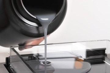
A lot like with some of 3D-printing filaments used during FDM, the temperature of your room also has an important influence over the photopolymer resin in SLA manufacturing process. Proper temperature is one of the main conditions that decides whether the resin will set or not.
If the resin is not hot enough, the odds are it won’t set at all. If it does, however, it will result in overall inconsistency i.e. poor plate adhesion and partly-finished prints.
Unfortunately, we can’t really find a particular reason that causes this problem to appear. In some time, we are going to find a filament scholar that will kindly explain it all to us, but until this… the reasons are vague. Maybe one of the readers could give us all a hint in the comments? However, it’s not really obligatory to understand the roots of the problem in order to solve the issue.
You need to know that the resin needs to be stored in a warm room, and It’s also important to ensure that the printing process is carried out in warm conditions too. Some of the filaments may require a temperature of 25-30°C (77-86°F) in order to set properly.
Printing room being too cold is usually the case with cold climate countries. In order to ensure optimal temperature conditions when working with resins simply move the printing device to a generally warmer room and place it near the source of heat. This is an easy fix, since there is more likely to be enough heat to make the resin operable.
Another quick solution is to obtain a heated chamber. Some of them are relatively cheap (60-100$) and feature a heater, fan, thermostat and also a power supply. Of course, another way to deal with this is to build your own heated chamber for even cheaper price, but in order to deal with the problem as soon as possible you may want to just buy the simplest one.
Establish warm temperature conditions
Obtain a heated chamber
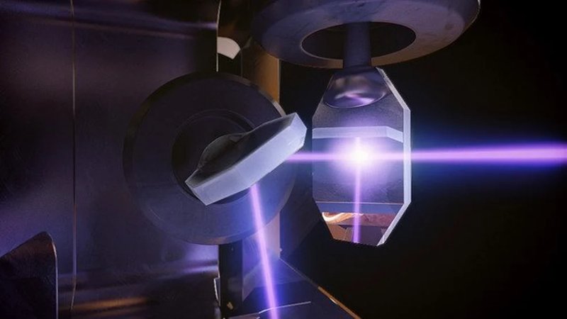
When it comes to SLA printing technology, a photopolymer resin has to be hardened by means of a UV-light source - a laser, usually. In order for the manufacturing to go smoothly, the resin must receive a sufficient degree of UV-light exposure before solidifying.
If the resin was underexposed to a UV-light source, nothing will come out of your printer or the printed model will become so faint that it won’t resist the peel force of your printer. Generally, underexposure appears when the laser is moving too fast which is the topic of this subsection, or if it doesn’t have enough power which is the topic of the next one.
For most of the SLA printers, it’s possible to adjust the print speed in slicing software settings to quickly fix the problem. Be aware, however, that oftentimes your device is unable to print anything because the resin is too cold, which was analysed in the previous subsection. Heating the resin up will most often fix the problem, but if that didn’t work, try decreasing the print speed.
Adjust the print speed
Using an insufficiently powered laser causes your resin to be underexposed to the proper amount of UV-light, just like in case with laser moving too fast.
The name of the problem is quite self-explanatory really, so the obvious answer is that your laser is underpowered. In order for the resin to become properly polymerized, the laser needs to be supplied with a sufficient amount of energy. And just like with the previous issue, a laser with too low power is unable to transfer enough UV-light to the resin in order to start the printing process.
If you own a printer that provides the possibility of manual laser power adjustment, try increasing this value by very small amounts. You might as well be able to find out the optimal exposure conditions that perfectly match the resin and print speed you’ve been utilizing.
ATTENTION: Be aware that topping up the laser power is your last hope. Make sure to adjust the value carefully and resort to it only if nothing else helps or you want to apply the settings recommended by the manufacturer of your resin or printer. Setting the laser power too high often cause the appearance of ‘bloomings’ on your printed models. This means that the areas around the spot that the device is supposed to set will be exposed, causing abnormal surface finish. Moreover, this may harm the interfacing level that’s located at the bottom of your printer’s resin tank.
Carefully adjust the laser power
Everything was going perfectly fine until a sudden malfunction appeared and brought in the force of destruction. With a sinking heart, you observe your model failing to be completed correctly. This may be caused by different reasons — let us review the most popular ones.
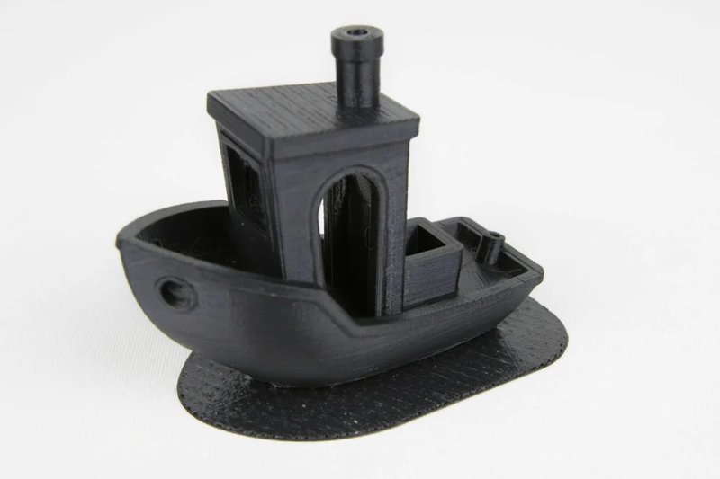
The support base of your model isn’t adhering to the print plate. It may be partially exfoliated or completely detached, gliding around the resin tank.
This particular problem is caused by several reasons. The first fault is at the printer’s side — it may provide incorrect repositioning to the next printing layer. This creates an excessive degree of peel strength that's too much for your device to properly operate with.
In case of top-down SLA printing, peel strength represents the suction applied on prints every time the print plate and bottom side of the resin vat are detached in order to carry out repositioning. The mechanics of this action are printer-specific, therefore different devices require different solution in order to fix the problem or at least minimize its consequences.
One more factor that possesses a great influences over the degree of print’s adhesion is correctly prepared print plate. In case of bottom-up SLA printers, the best decision is to manufacture your models onto a finely textured level metal plate. And on the contrary, the interfacing layer located in the resin vat may bear signs of ghosting and prevent the laser from setting the resin appropriately.
Another issue is that the resin may simply not be warm enough in order to set properly. This often happens during continuous printing sessions when the resin level decreases to some extent and an insignificant temperature change prevents the resin from setting.
If the resin vat your machine employs is a tilting one, it creates different zones across the plate where the peel strength varies from very strong to very weak. An interesting remark — tilting vats were specifically created to address the issue of too much peeling strength.
In order to solve the problem, place the print to a zone that’s exposed to the least amounts of peel strength, which ensures a good bonding with the plate. Moreover, placing the print inside of these zones decreases the amount of stress applied on higher parts that are either standing without supports or rely on them.
Poorly leveled bed is a scourge of both FDM and SLA 3D-printing devices. Depending on the machine, you’ll be able to make some level adjustments (either automatic or manual) to your bed or vat. If the case is that only one part of your printed model properly sticks to the print plate, then the cause of the problem might be that the same particular part of the plate is not firmly aligned to an interface layer in the bed during the operation of laser. An additional sign that the issue has appeared is a flat disc of hardened resin that’s located inside the vat and stuck to your interface layer after finishing or cancelling the manufacturing process.
Look for specific recommendations on the matter of bed leveling for your particular device. Also, be sure to find a piece of advice on advanced calibration and give it a try.
If your printer is finely calibrated and set up but you still experience the problem, the chances are that something is not right with the resin hardening. If the resin is too cold it won’t be able to set properly, and a as a result won’t stick to the print plate. You should try and heat the resin and print chamber by moving your device to a warmer room and placing it near a source of heat.
The interface layer is a subtle layer of jelly-like material that a whole lot of SLA 3D-printing machines make use of. This layer is located on the bottom side of the acrylic resin vat. In case of inexpensive bottom-up resin printers, the print plate comes in contact with the interfacing layer in order to obtain a small film of resin to set the following layers. The wearing of the interface layer is impossible to avoid, as well as its consequences like ghost marks and general decrease of product quality. Severe wearing makes specific print plate areas (usually those that were used the most) to become completely unsuitable for printing. The main solutions are to either buy a new interface layer, substitute the layer you currently use with a self-made one or buy a new vat. You may also just keep on relocating your prints until there is no more areas suitable for printing.
After successfully manufacturing a couple of prints, you may often find a few particles of resin swimming on the surface inside your vat. These particles are extremely important to remove since they may cause a laser malfunction — it won’t longer be able to cure fresh resin properly. Therefore, it’s a good idea to go over the vat every now and then not only to remove the above-mentioned parts but also to remove any resin that got stuck to the bottom of the tank.
After cleaning the vat and leaving the printer for a couple of days, there is a possibility that the resin mixed up with a thicker pigment from dyed resins. As a result, it leads to a creation of a new inconsistent layer that is not quite proper to utilize.
In case of freshly-bought SLA 3D-printing devices, the plate they are supplied with can be literally too perfect to print on. In order to fix this, try and sand the print plate carefully with a medium grit sandpaper. Make sure to neatly clean the plate after sanding, since if some of the remnants meet the resin you’ll be experiencing printing problems.
Change the print location
Level the bed
Increase the temperature
Replace the interface layer
Clean the resin tank
Mix the resin once again
Sand the plate
During the manufacturing process, a big piece of hardened resin has detached either completely or partly and moved just enough to spoil other parts of the product.
In some cases, the problem appears due to incorrect orientation of the print, meaning that it won’t be able to withstand the peel strength. This will cause the movement distortion which in its turn leaves you with another problem — the successive layers will be created on the vat interface instead of print itself.
Aside from incorrect orientation, weak support structures might be another cause for the problem.
There is also a chance that only some areas of the print such as cross sections are getting messed up by excessive peel strength. In case your print is hollowed, the reason might be that there is not enough drainage holes to properly mitigate explosions.
If your prints require wide surface area at any step of the manufacturing, consider making them hollow and then supply them with drainage holes, if possible.
In essence, you obtain a smaller outline of your model that is pulled away from the resin vat, rather than detaching wide flat surface every time the layer changes.
Hollow prints require far less force and won’t usually spoil your model, provided that you’ve added some drainage holes with the software. If the holes are missing from the solid masses, you will basically create a container with unset resin which is a waste of resources.
If the model seems okay to print, but you doubt that the peel strength is innocent of failed prints, strengthening the support structures is another solution. Widen the points where the structure and print interconnect by a fraction of a millimeter and add racks between them.
Adding more support structures is another solution, though you’ll have to address the issue of increased post-processing clean up routine after you finished the printing.
A possibility is that your print platform isn’t fixate enough. As the machine creates layer after layer while stepping the platform accordingly, small dispositions caused by platform movements tend to misalign or even separate or delaminate the layers.
Improved model orientation can fix a lot of problems that appear in SLA 3D-printing. Not only it increases the probability of a successful print, but also improves its quality and reduces the stress in the tank.
In order to orient the model in a best way possible, take the following points into consideration:
Position. If you position the print inside the zone that has weake peel strength, you increase the chances of a successful result. An overwhelming amount of bottom-up SLA 3D-printers work on the basis of peel mechanic. It is used to detach the print plate from the bottom side of the resin tank when moving to another layer, following Z-axis.
Overhangs need to be supported. If the overhangs you use are quite large and overall difficult, they’ll need some sort of support, just like in FDM 3D-printing.
Moreover, the 3D-models can be tweaked in order to avoid creation of supports to some extent. Try decreasing the overhang angles and adjusting the model so it will be properly printed without supports.
Minimum Points (Minima). Minimum points represent individual parts of your print that are isolated from the rest of it, i.e. the zones which are not directly connected to the print body. As in case with overhangs, minima need to be modified with support structures in order to prevent them from detaching and entering the resin tank.
As with the case of overhangs, you are actually able to bypass the need for creating support structures for minima too. Try tactical model orientation.
Cupping. If the model you’re planning to manufacture has gaps that have access to the print vat (like in case of hollowing), it may cause the excessive peel strength that your model just won’t be able to withstand. As a result, the print will be defected.
If this “cup” appear to be small, try angling your print in order to decrease the cupping to the point where your product won’t get destroyed.
Another solution is to provide your model with drainage holes, which would ensure that the resin flows through during each consecutive layer change.
Make large prints hollow
Reinforce the supports
Fixate the print platform
Improve the orientation of your model
The printer has successfully operated for a bunch of hours and alas! The print is finally finished. The only problem is that it looks like trash.
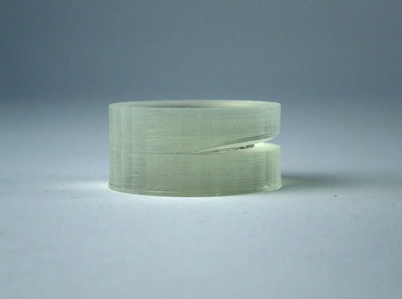
Some areas of the printed model are looking shabby, and the layers that don’t bond properly can get pulled apart.
Delamination is a popular SLA 3D-printing issue that is characterized by poor layer bonding and has a number of different causes.
Improper print orientation is one of such cases — it usually appears if you didn’t tweak the print well enough to avoid minimum points. In short, these points are high locations that are separated from the print body, that on the contrary is properly attached to the printing platform. If unsupported or without adjustments, such structures will frequently get separated from the rest of the product and ruin it in terms of both quality and appearance. Therefore, be sure to provide minimum points with support structures or just adjust their angles to a lesser degree.
For more reasons, the layer separation can also be caused by debris, incorrectly mixed resin or ghosting of the resin tank. All of those are pretty easy to deal with.
This problem may also suddenly appear in the middle of the post-processing stage. If the material used for the printed model has a weak layer bonding and you left the printed detail in IPA for too long, the chances are that the layers will be furtherly weakened and your print will fall apart.
It is important to modify minimum points with support structures, otherwise the print will surely get deformed. It is important to provide supports to structures with difficult angles and to the highest points of zones that aren’t connected with the print body. The total amount of supports can be decreased by smartly orienting your print on the plate, so be creative.
This solution addresses all the requirements that need to be met in order to ensure that the laser will have a clear access to the resin.
First, check that the resin you utilize is “purified” and doesn’t contain any unwanted particles. In order to do this, you might want to use a resin comb or to make the resin leak through a filter to remove any tiny parts that were left after previous printing sessions.
The following step is checking the interface layer. If you already printer with the tank you utilize, be sure to check it for ghost marks on the interface layer. Over time, such marks can increase and as a result block the laser access which will cause weaker, or even totally deformed prints.
If you feel that your interface layer is done for, then you know it’s time to buy a new one. Depending on the printer, you may as well need to buy a new tank. .
Self-explanatory. If the printed part has weak bonds between the layers, don’t weaken it any more by letting it bath in IPA for too long. Before rinsing, be sure to mix the unset resin in a careful and quick manner.
Place some support structures
Pave the way for the laser beam
Optimize the IPA wash cycle
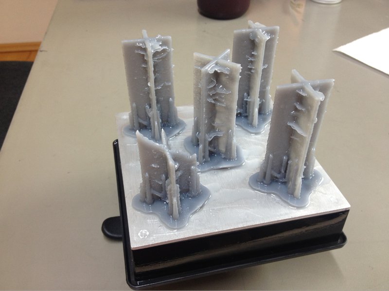
These ugly-looking flaps are covering the print, accompanied by a bunch of deformed offsets that were definitely not designed to be there.
The most likely cause of this problem is unclear optical path. Because of this, the laser can sometimes protrude to the resin areas that weren’t supposed to be reached.
Here’s a list of other factors that have a potential of escalating the problem even further: settled resin, big set particles that got mixed with the utilized resin, and overall unclean pathway between the laser and resin.
Remove any pieces of resin that were left after previous printing sessions by means of a filter. Such filters tend to be particularly effective in terms of this solution and can be easily bought at any decent 3D-printing shop. If the resin is not filtered properly, the odds are it will get clouded in the middle of 3D-printing.
In case that your resin was unused for quite an amount of time, there’s a good probability that it in fact settled and two separate layers were formed - a thicker one with the pigment and a thinner one with the photopolymer. Make sure to mix the resin once again in order to even the layers.
Your printer may not feature access to it, but if it does, be sure to try it. Locate the transparent barrier that secures the galvanometers and clear it from debris, dirt, dust and other obstacles that block the optical path.
Filter the resin
Mix the resin once again
Pave the way for the laser
Update your browser to view this website correctly. Update my browser now
Write a comment