A large number of various 3D printers is running on the popular Marlin firmware, which was initially configured for Ultimaker Original. Let's take a look at the basic settings for other 3D printers.
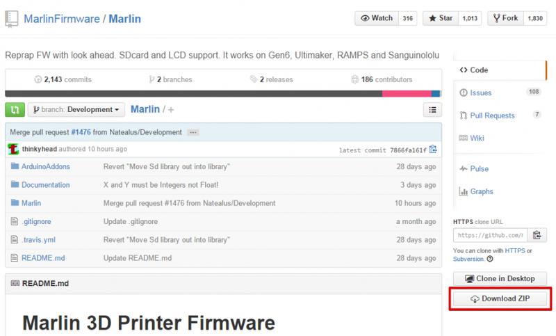
The firmware is available here. Download the Marlin-Development.zip archive by clicking the Download ZIP button. Unzip it into a folder of your choosing.
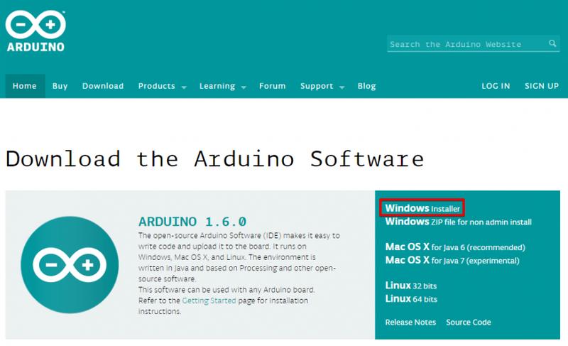
Now download Arduino IDE for setting up and uploading the firmware to your 3D printer. Link. Click on the Windows Installer button and download arduino-1.6.0-windows.exe. Now launch it and install Arduino IDE.
Open the firmware folder and run the Marlin.ino file.
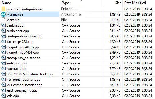
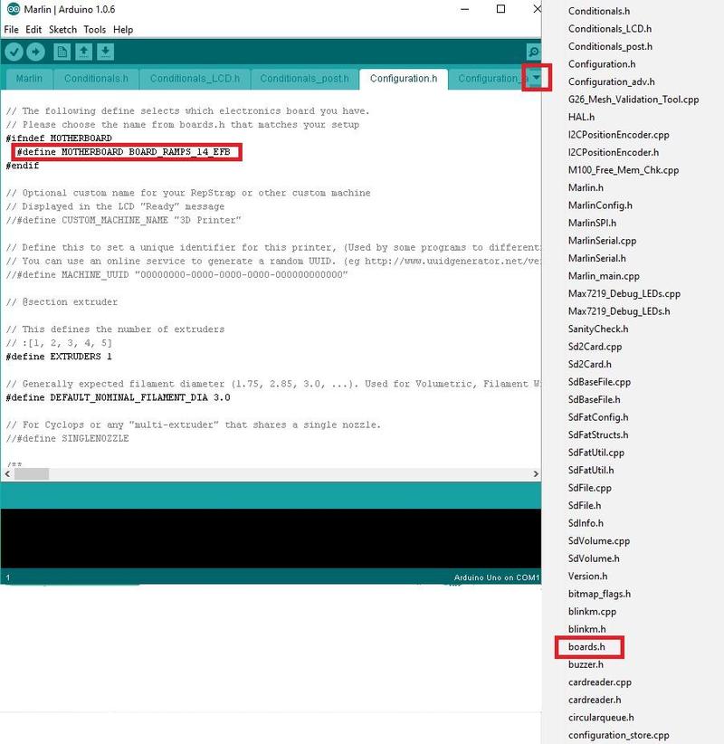
The firmware is then opened by the Arduino IDE editor. We need to open the Configuration.h tab.

In this section you’ll see various links for 3D printer calibration and several basic settings (e.g., type of electronics, type of temperature sensor, LCD controller etc).
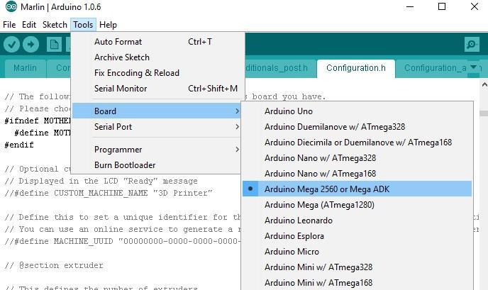
Let's start by choosing your controller (MOTHERBOARD). The list of controllers is available in the boards.h tab. Click on the triangle icon in the upper right corner and select boards.h.
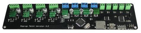
Now let's take a look at the installed hardware. Here are some of the board types:
Melzi
RAMPS 1.4
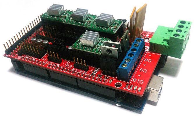
We have RAMPS 1.4.
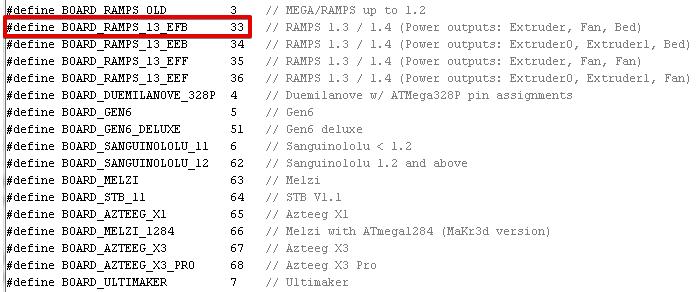
So, we need to replace the “MOTHERBOARD BOARD_ULTIMAKER” line with “MOTHERBOARD BOARD_RAMPS_13_EFB” in configuration.h.
#ifndef MOTHERBOARD
#define MOTHERBOARD BOARD_RAMPS_13_EFB
#endif
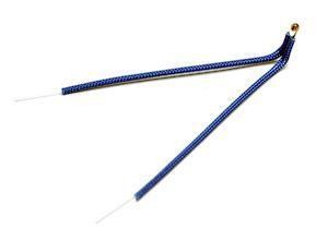
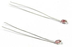
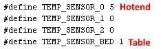
Next you’ll need to select the temperature sensor – choose thermally sensitive resistor. You can see a large list called “//// Temperature sensor settings”. In this particular case, we have an E3D-v5 hotend and a Chinese thermal resistor on the table. For E3D-v5 we select “// 5 is 100K thermistor - ATC Semitec 104GT-2”, for the table – “// 1 is 100k thermistor - best choice for EPCOS 100k”. You can select 1 if you don’t know the type of the thermal resistor. You’ll be able to select any of them and try them out if the temperature is not to your liking. We're changing the values.
100K thermistor - ATC Semitec 104GT-2
A common Chinese thermal resistor 100K
The maximum limit of the hotend temp “#define HEATER_0_MAXTEMP 275”.
The minimum limit of the hotend temp “#define EXTRUDE_MINTEMP 170”.
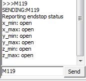
If the limit switch is connected in an irregular fashion and its function needs to be inverted, this can be done in the firmware itself without resolder the connectors. The values are false or true. The M119 command (e.g. in Pronterface) shows the status of the limit switches. Our limit switches are set to the HOME position on MAX.
At the HOME position

At positions other than HOME along all axes
We didn’t have to change anything.
const bool X_MIN_ENDSTOP_INVERTING = true;
const bool Y_MIN_ENDSTOP_INVERTING = true;
const bool Z_MIN_ENDSTOP_INVERTING = true;
const bool X_MAX_ENDSTOP_INVERTING = true;
const bool Y_MAX_ENDSTOP_INVERTING = true;
const bool Z_MAX_ENDSTOP_INVERTING = true;
Changing the rotation directions of the stepper motors, values are false or true. Correct nozzle movements relative to the table:
- On the X axis - to the left “-“, to the right “+”.
- On Y - forward “+”, backward “-“.
- On the Z axis - closer “-“, farther “+”.
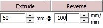
- Extrusion device. “Extrude” - extrusion of the thread, “Reverse” (retract) - retraction of the thread.
#define INVERT_X_DIR false
#define INVERT_Y_DIR false
#define INVERT_Z_DIR false
#define INVERT_E0_DIR true
Next are the settings of the limit switches. We need to find out where they are located – the point of origin is in the near left corner of the table. If the nozzle reaches this position, the MIN switches will activate; if it reaches the upper right position – it will trigger the MAX switches. We have three MAX limit switches at the HOME position, our settings are as follows:
// Sets direction of endstops when homing; 1=MAX, -1=MIN
#define X_HOME_DIR 1
#define Y_HOME_DIR 1
#define Z_HOME_DIR 1
Then we need to set up the dimensions of movement after the startup in the HOME position. We can set the dimensions of the working area in the X and Y axes as well as the nozzle setting relative to the table.
If the limit switch (MIN) is triggered when the nozzle touches the table (as in the case of the Ultimaker Original), the nozzle can be adjusted to the table by moving the limit switch. We need to put the coordinate value at the maximum distance from the table to the nozzle in the “#define Z_MAX_POS” line. You can find the needed value by using the M114 command or by looking at the display.
If the limit switch in the Z axis is activated when the nozzle is farthest from the table (MAX), you’ll need to find the Z dimension values yourself. We initially set the value “#define Z_MAX_POS” higher than normal, for example we use 250 with the dimension of 200 mm. We can lower the nozzle until it touches the table so that we can see the value greater than zero on the display (or by using the command M114), which we subtract from the set higher value and get the needed Z dimension. We then write it in the ”#define Z_MAX_POS” line. You’ll be able to adjust this value accordingly after printing the first layer based on the results.
// Travel limits after homing
#define X_MAX_POS 215
#define X_MIN_POS 0
#define Y_MAX_POS 215
#define Y_MIN_POS 0
#define Z_MAX_POS 200
#define Z_MIN_POS 0
You can adjust the movement speed at the HOME position.
#define HOMING_FEEDRATE {50*60, 50*60, 4*60, 0} // set the homing speeds (mm/min)
Now let’s move on to the most important part – setting the steps per unit for one or more axes. The extrusion device is also an axis. Here are our settings:

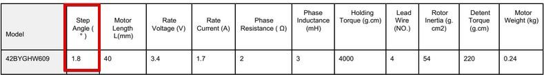
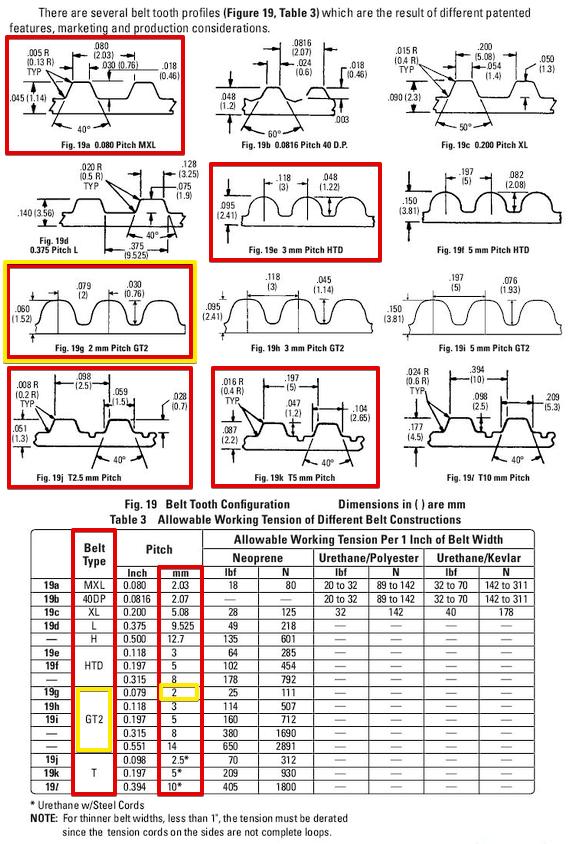
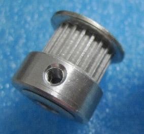
Now let's see how we set them. There are stepper motors on all axes, 200 steps-per-revolution, 16 micro-steps per step (determined by the jumper pins on the board). The X and Y axes are equipped with a GT2 drive belt with the screw pitch of 2 mm and 20 tooth pulleys, which in total brings us to this formula: (200*16) / (2.0*20). The Z axis has M8 threads with the pitch of 1.25 mm, the total formula is 200*16/1.25.
We can find the needed specs (data sheets) for installed stepper motors, in which we see that the shaft rotates 1.8 degrees in one step, which means 360/1.8=200 steps per full revolution. This parameter is the same for most home 3D printers stepper motors.
Belt profiles commonly used in 3D printers and their pitch. Original link, page 61.
Pulley
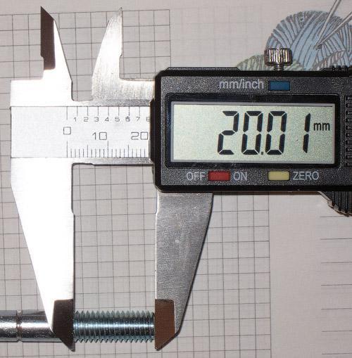
How to measure the screw pitch?
We can measure the screw segment and count the turns on it, then divide the length of the section in millimeters by the number of turns: 20/16=1.25 mm. We can measure the maximum length segment for more accurate results.
The process of setting up the extrusion device depends on the reduction ratio and the diameter of the feed gear. Let’s select some values by experiment after the initial upload of the firmware. Unscrew the nozzle and reduce the minimum nozzle temperature limit to 5 degrees: “#define EXTRUDE_MINTEMP 5”. Now the extrusion device will function with a cold nozzle, which is exactly what we need. Let’s maintain these settings for the time being. We use Pronterface for the setup. We put in the following values: 50 mm and the speed of 100 mm/sec (50 mm is the length of the bar passing through the extrusion device; we can measure the length of the bar passing through the extrusion device with a ruler or a caliper gauge).
By tinkering with the extrusion device settings, wee then find the exact needed value at a reasonable bar length, let’s say 300 mm. After setting it up, we will go back to the minimum temperature limit: “#define EXTRUDE_MINTEMP 170”.
The following values are the limits of the maximum axial speed. We put in 200 mm for the X and Y axes and didn’t change the rest.
#define DEFAULT_MAX_FEEDRATE {200, 200, 5, 25}
Setting up the acceleration of axial movements. Step skips are possible with high enough acceleration values. You can find the proper values by experimenting in Pronterface with the tests at any given speed. Here are our settings:
#define DEFAULT_MAX_ACCELERATION {1000,1000,100,10000}
#define DEFAULT_ACCELERATION 1500
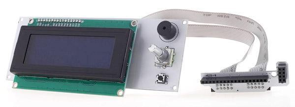
Finally, we need to activate the LCD display with an SD card. This particular display was found at RepRap.org and identified it as the RepRapDiscount Smart Controller.
Let’s uncomment (remove double slashes) the following lines:
#define ULTRA_LCD
#define SDSUPPORT
#define ULTIPANEL
#define REPRAP_DISCOUNT_SMART_CONTROLLER
There is one more tweak to increase the accuracy of some limit switches’ function. When we set the Z value to zero, we’ve ran into the issue of the nozzle located above the table slightly changing its position after each HOME initialization. Having rummaged through the firmware, we found the parameter responsible for the startup of the limit switches – we need to open the Configuration_adv.h tab and look for the “#define Z_HOME_RETRACT_MM 2” line. We then change the value 2 to 5 and gleefully forget about this parameter forever.
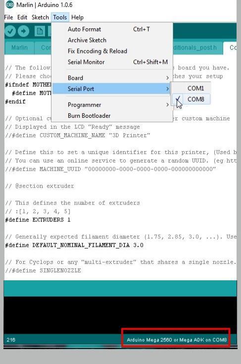
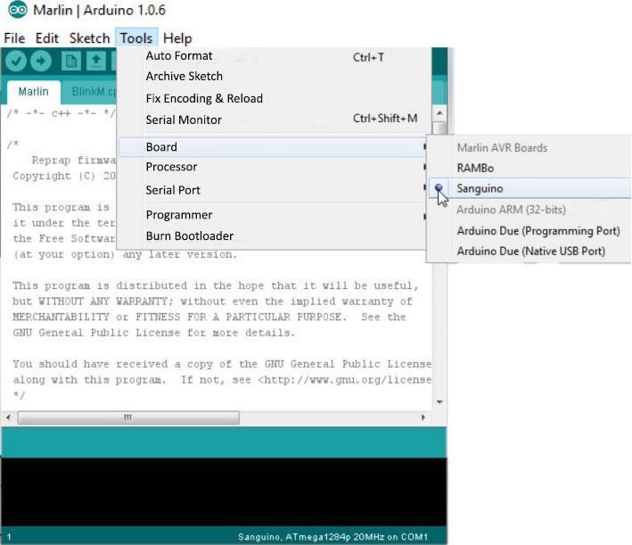
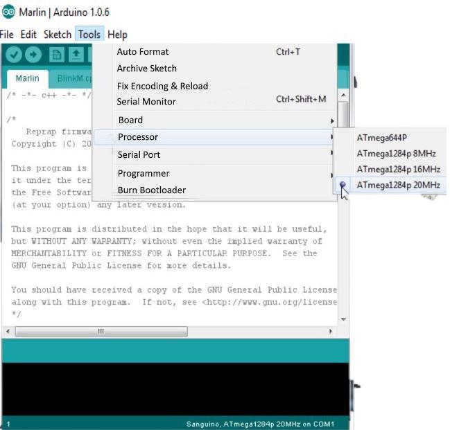
It is now time to upload the firmware to the controller. To do this, we need to correctly put the board type and COM port number in Arduino IDE. At the bottom of the window you can see the board type and port number being displayed. Do not forget to save your changes (Ctrl+S) .
RAMPS
MELZI
In order to be able to select the desired board in Arduino IDE, you first need to copy everything from the firmware folder “Marlin-DevelopmentArduinoAddonsArduino_1.5.xhardwaremarlinavr” to the Arduino IDE folder at “C: Program Files (x86) Arduinohardwarearduinoavr”'. This lets you choose the Sanguino board (base board for Melzi) and the desired processor type. We don’t have a Melzi board, so we can’t check its functionality with the software.
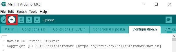
Click on the circle with the arrow icon to upload the firmware.
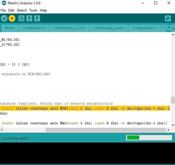
Firmware upload progress is showed by the indicator
You’ll need to run the PID calibration for heating the hotend and the bed after making sure that everything is working properly. For this, we use Pronterface. Enter the following command: M303 E0 C8 S260, where M303 is the calibration command, E0 is the hotend, C8 is the number of heating-cooling cycles and S260 is the standard nozzle operating temperature.
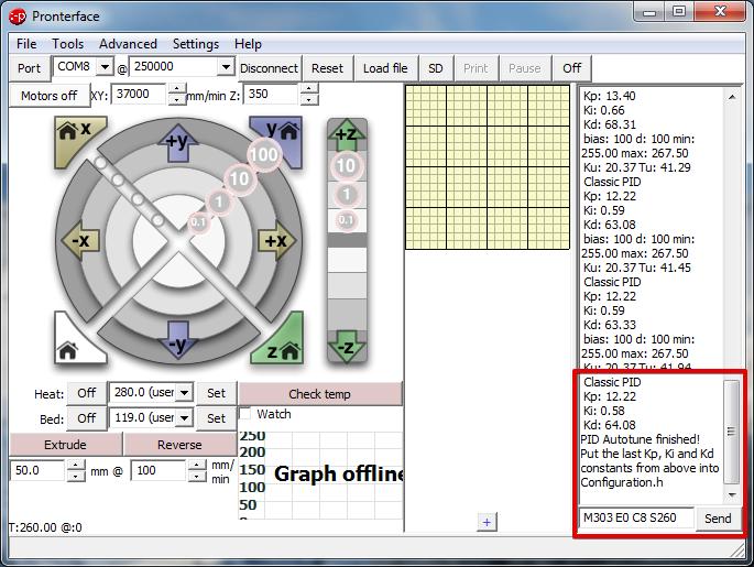
We then enter the results in the firmware.
#define DEFAULT_Kp 12.22
#define DEFAULT_Ki 0.58
#define DEFAULT_Kd 64.08
After that, we calibrate the bed PID using the same method. Enter the following command: M303 E-1 C8 S110, where E-1 is the bed and S110 is the standard bed heating temperature. Enter the results in the firmware. Our table heats up very slowly, so we have to restart the command due to a Timeout error.
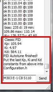
#define DEFAULT_bedKp 105.94
#define DEFAULT_bedKi 4.97
#define DEFAULT_bedKd 564.11
Where can I find the default parameters of my 3D printer to avoid recalibration?
The default parameters set in the firmware can be found by using the program Repetier-Host in the EEPROM Settings menu. First you need to specify the COM port in the settings and click the Connect button.
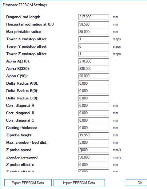
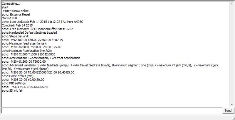
The list of firmware parameters is displayed in the right section of the window when you connect your 3D printer to Pronterface.
The parameters can also be seen on the LCD display via the ControlMotion menu.
Update your browser to view this website correctly. Update my browser now


Write a comment