
Thor3D was founded by a team of talented engineers and mathematicians. In 2015, they introduced the Thor 3D scanner, which was the first wireless 3D scanning device on the market. The next model called Drake was released in 2017. Both Thor and Drake have already been discontinued and replaced by the Calibry series of 3D scanners available in two versions: namely, Calibry and Calibry Mini.

So, today we will talk about the Calibry Mini model. For the original Calibry, read the corresponding article.
The designation ‘Mini’ does not presuppose that this scanner is smaller or less efficient. The difference lies in the size of the scanned objects. At the same time, the proprietary Calibry Nest software allows users to engage the scanner models in conjunction and align scans of the same object obtained from different devices.
The Calibry Mini is powered by structured light technology. A small LED emitter that projects a special blue grid on the scanned object is located in the center of the front side. The camera, which is located on top, captures the distortion of this grid. The software computes the distortion of the grid and uses it to determine which sections are closer or further away. The camera in the center is responsible for scanning the textures of the object, delivering full-color 3D models.
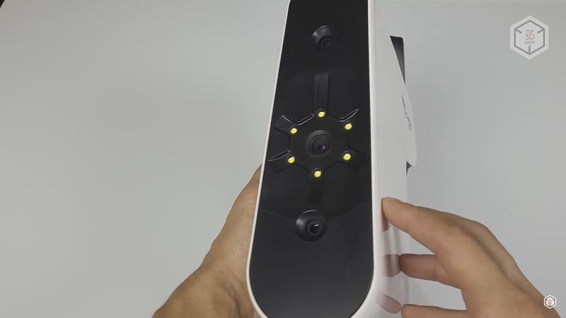
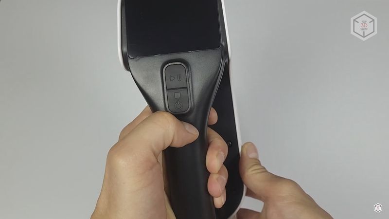
As with most handheld 3D scanners, there is a handle on the back for easy wielding. The top section of the handle houses two buttons, with one responsible for starting and pausing the scan, and the second button for stopping and turning off the scanner.
In addition, the bottom of the scanner has a threaded hole to install the device on a tripod.
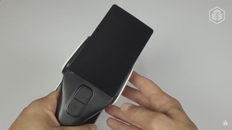
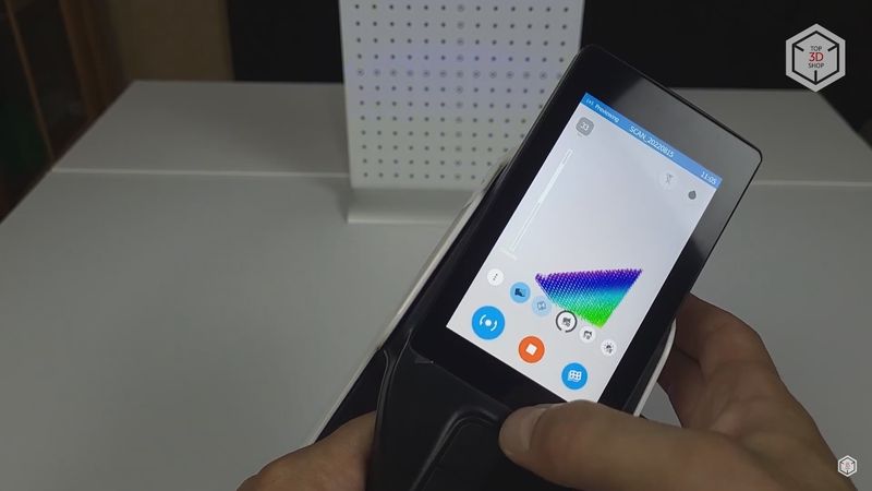
Also, one of the important and advantageous differences of Calibry scanners is the 4" touch screen which is used for both configuring the basic parameters and monitoring the scanning process. This is very convenient compared to scanners with no touchscreen and monitoring the scan through a screen of a computer or laptop.
You can find the full list of technical specifications of the device below.
The 3D scanner is supplied with a Calibry Nest software license. In general, software plays a vital role in 3D scanning, since it is responsible for processing the data received from the device and converting it into a digital 3D model. Calibry Nest is a far fetch from an ideal program for these purposes. It is not quite easy to navigate and lacks some useful features. But after some time, you get used to the interface, and the provided tools are enough for a comfortable workflow.
In our tests, we will try to show and describe most of Calibry Nest’s features. But first let’s unpack, connect, and calibrate the scanner.
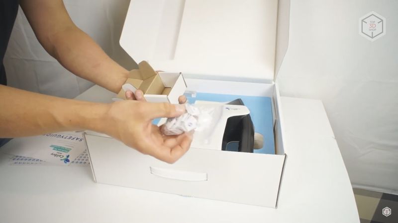
The scanner comes in a small cardboard box, which carries another white box with the Calibry logo, containing an aluminum stand for the calibration panel and the panel itself.
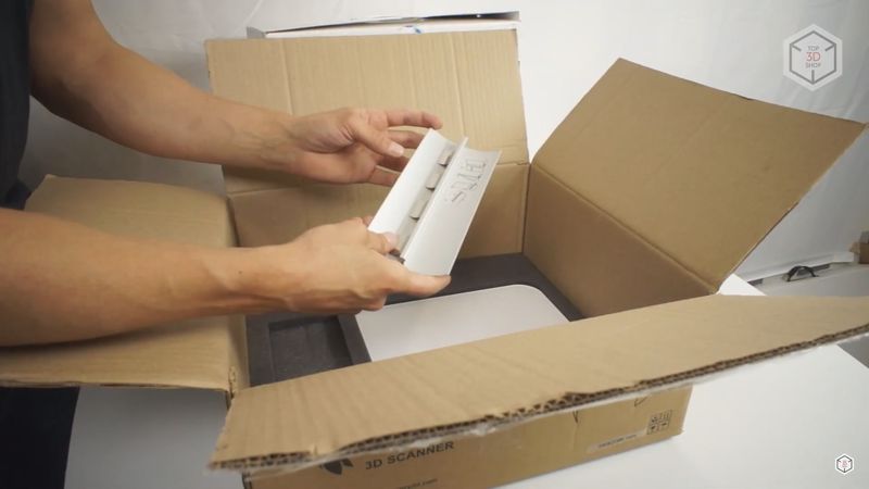
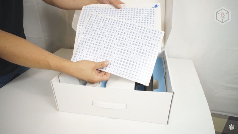
The white box also includes a set of markers, which need to be glued onto the scanned object. Then come the safety leaflet, user manual, and instructions for connecting the scanner.
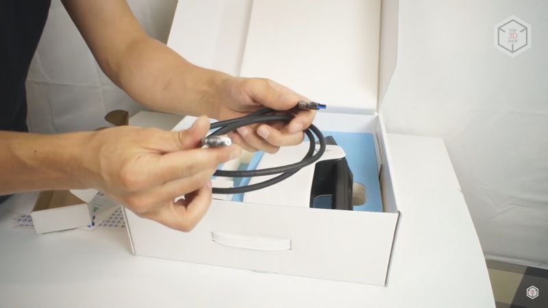
A 12 volt 5 amp Mean Well power supply is packed in a separate box with a long 5 meter USB 3.0 cable that is connected directly to the scanner.
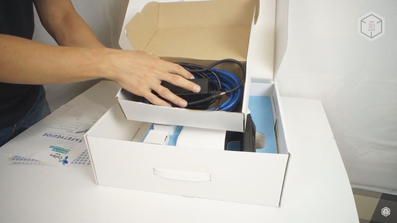
Next, we find another smaller USB 3.0 cable used to connect the device to the computer.
Another addition are markers printed on small cardboard squares that can simply be laid out around the object.
A small unit called the Power Injector serves as a hub and connects to the power supply and both USB cables. The connection procedure will be discussed in detail further.

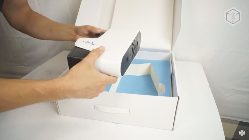
Next comes the scanner itself.
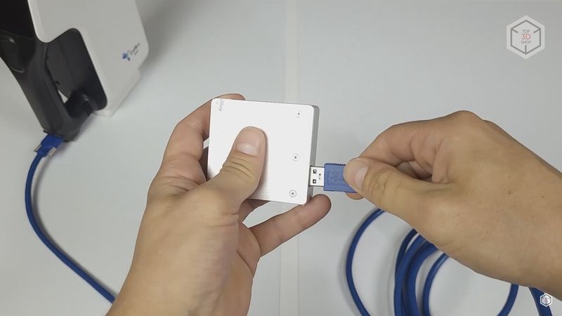
The first step is to connect the MicroUSB plug of the long blue USB cable to the scanner. It has special fixing screws, which need to be tightened well to guarantee good connection. The cable will inevitably bend when the scanner is moved around, and malfunctions may occur during operation if the plug is not properly fixed to the unit.
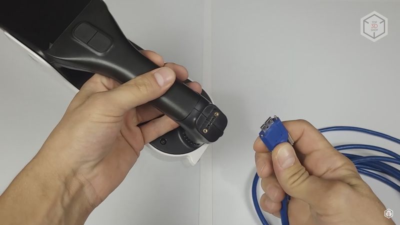
The full-size USB plug of this cable must be connected to the Power Injector which has only one corresponding port, making it impossible to mess up the connection.
Next, the MicroUSB plug of the second shorter USB cable is connected to the corresponding port of the Power Injector and also fixed with screws.
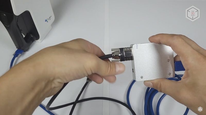
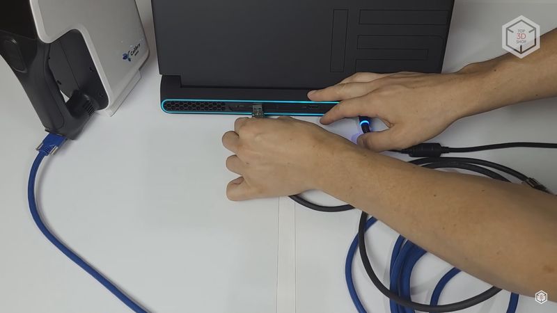
The full-sized USB plug of this cable goes into the computer, which should have a USB 3.0 or a more advanced port. During operation the scanner will send huge amounts of data to the computer, so extended bandwidth is necessary.
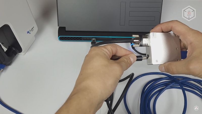
The last step is connecting the power supply to the Power Injector’s port.
At this point, the scanner is already up and running, but cannot be used since we need to install and start Calibry Nest.
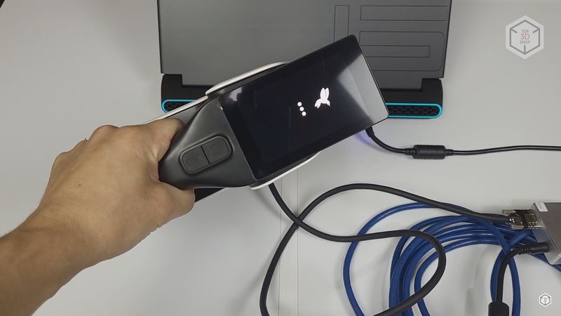
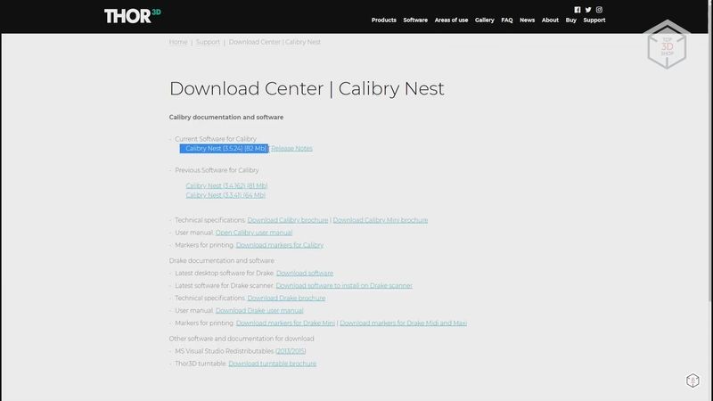
The latest version can be sourced from the download center on the company’s official website. The scanner will fully load after launching Calibry Nest, and its menu will appear on the screen.
Now we need to calibrate the scanner, which is an easy and straightforward process.
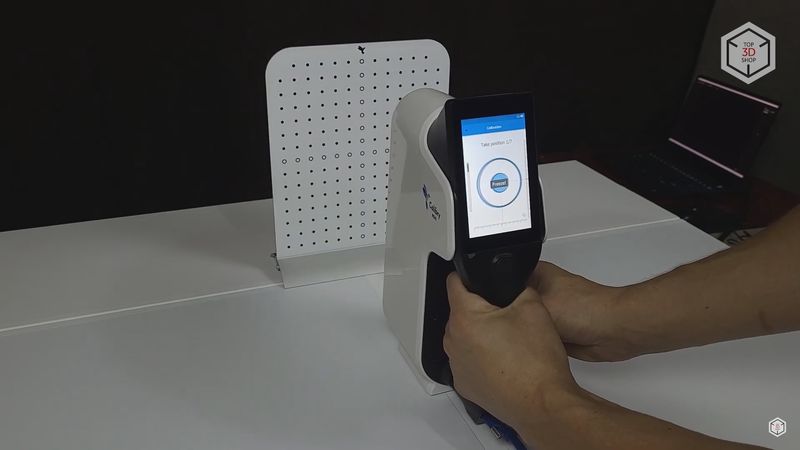
The calibration panel from the kit is tightly fixed on the aluminum stand. We placed them on a flat surface.
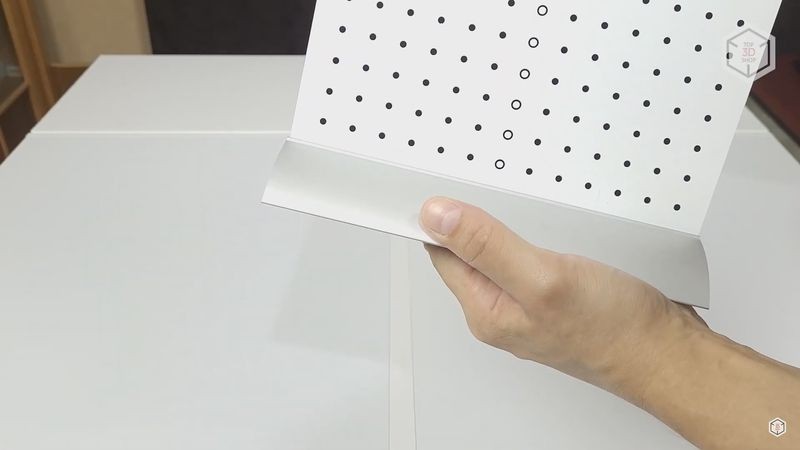
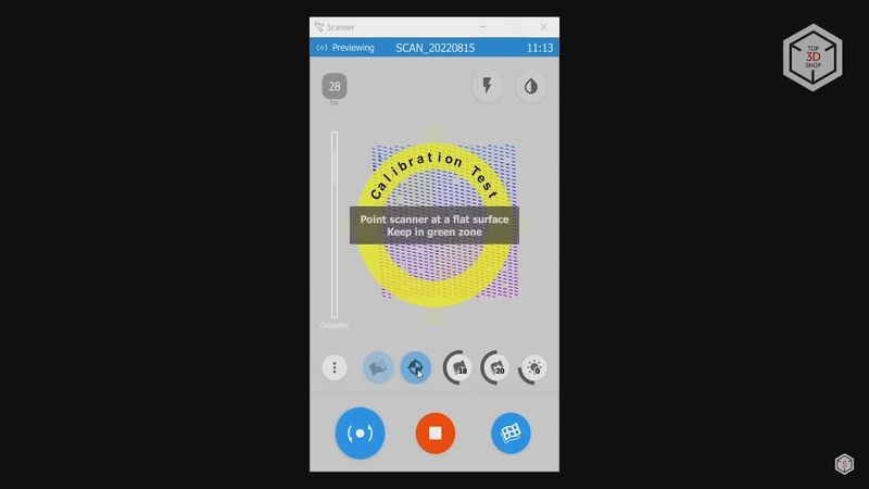
Press the button with three stripes on the scanner’s touch screen, choose the settings tab and select “Calibration”.
The scanner should be aimed at the calibration board before pressing the “Start” button. The screen will display two black and two orange circles. They need to merge together by moving and slightly turning the scanner. When the circles match, they will change color to blue and a “Freeze” command will appear on the screen. At this point, it is best to remove your hands from the scanner so that it does not stagger. Then the black and orange circles will appear again, and you need to move the scanner a little further away and repeat the calibration sequence.
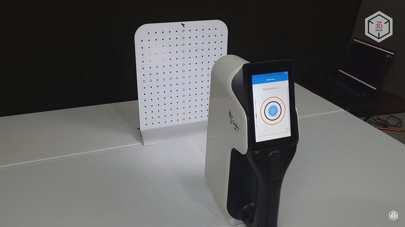
In total, this procedure must be repeated 7 times, gradually moving the scanner further and further away from the calibration panel. When all 7 steps are completed, the scanner will calculate the received data and reboot, which takes a minute or two.
It is advisable to repeat the calibration after transporting the scanner. If the calibration has not been performed within 3 days, the scanner will remind you to do so when you turn it on.
The initial setup is complete and we can start scanning.
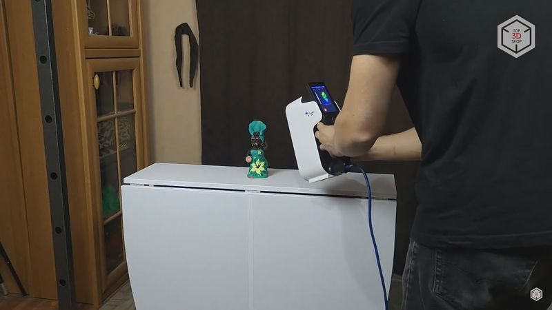
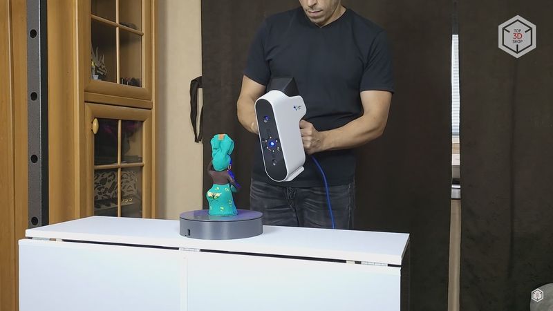
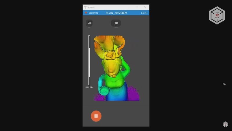
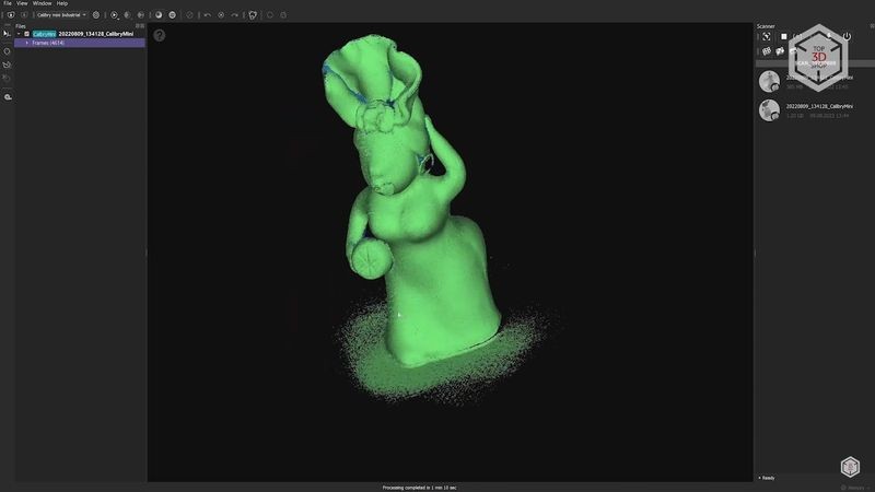
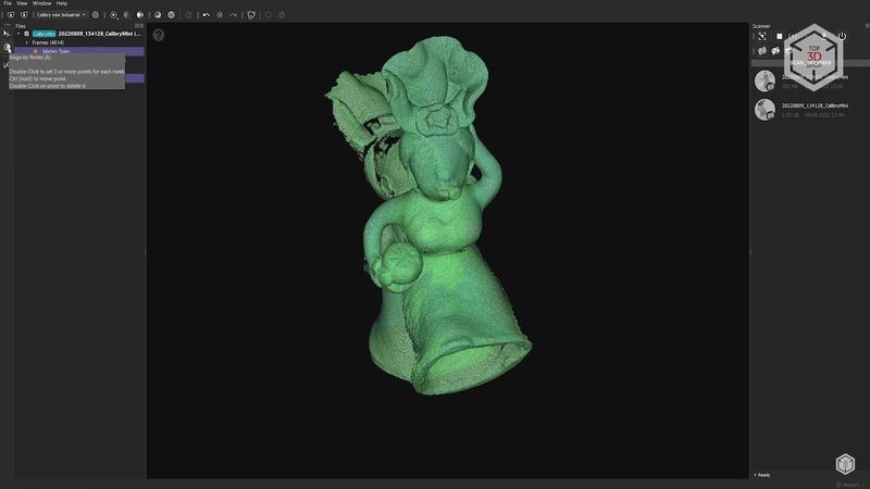
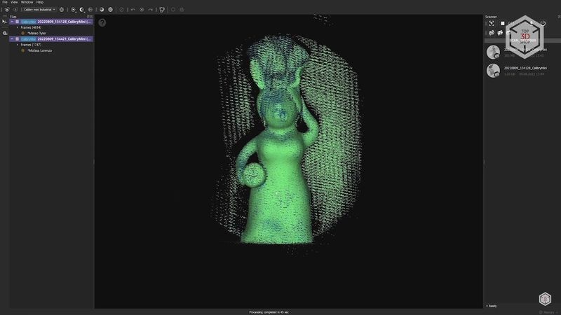
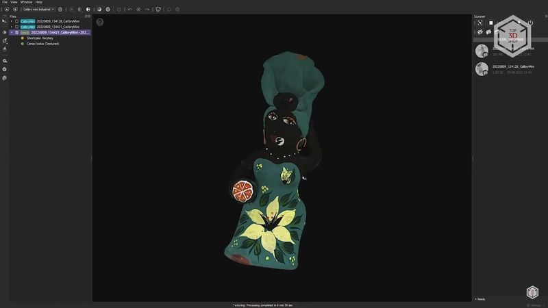
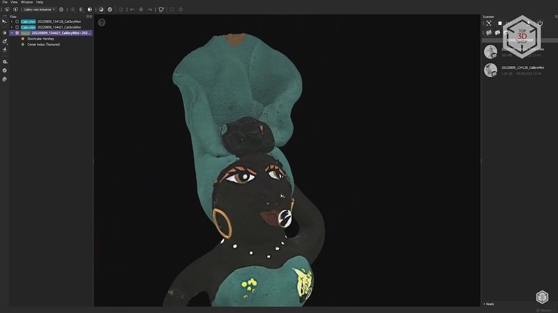
For the first test, we took an artistic multi-colored model — a small clay figurine of a Cuban woman. We will analyze this scan in detail to show as many features of the scanner and the Calibry Nest software as possible.

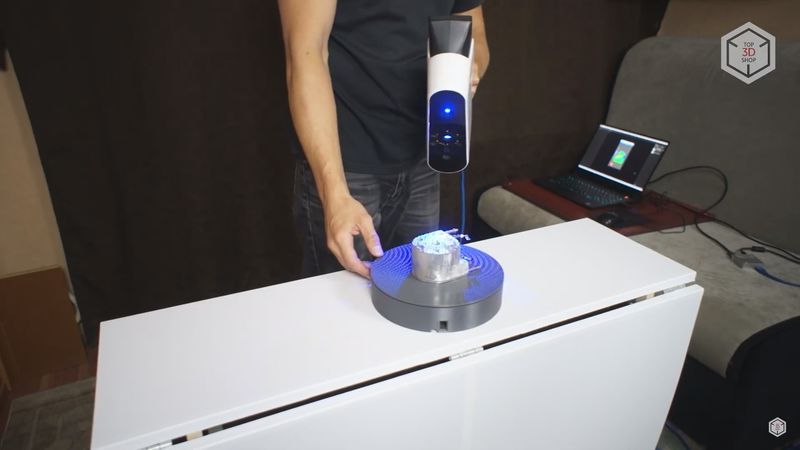
There are two main scanning methods. In the first one, the object is located on a fixed surface, and the scanner needs to be moved around the object.
For the second method, the object is placed on a rotating turntable while the scanner is held still in a stiff position. The table can be automatic, rotating the object by itself, or manual, where you need to turn it by hand to capture geometry from all the sides.
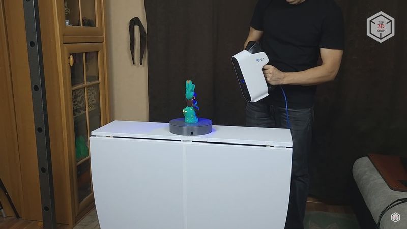
For most of our tests, we will be using a small 3D printed turntable. It is power-driven, but it turned out to be more convenient to rotate it manually and capture complex and hard-to-reach areas.
Now it is necessary to configure the scan settings, which can be accessed through the scanner’s touchscreen menu.
In addition, the screen interface can be opened in Calibry Nest on your computer by clicking the “Show Scanner Screen” button in the software. A separate window will appear with all the functions of the scanner’s screen. In some cases, this may be more convenient.
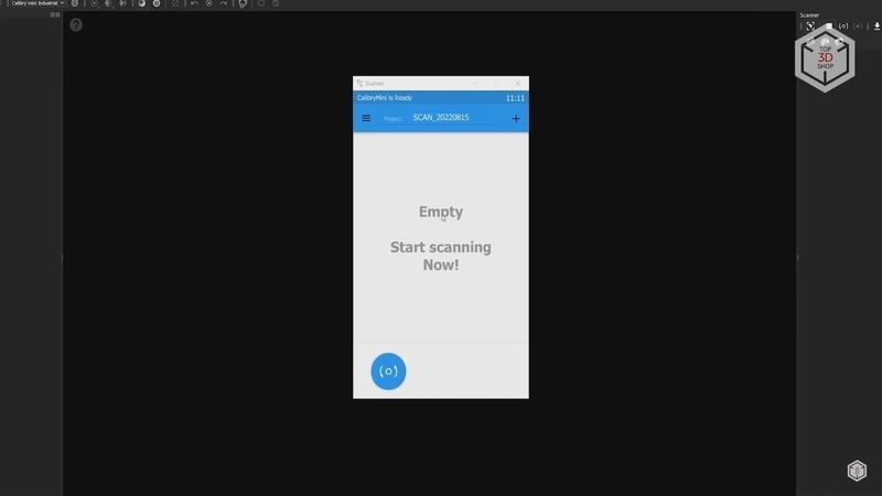
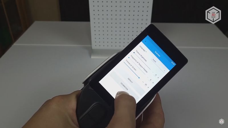
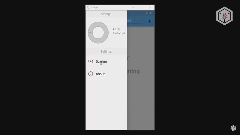
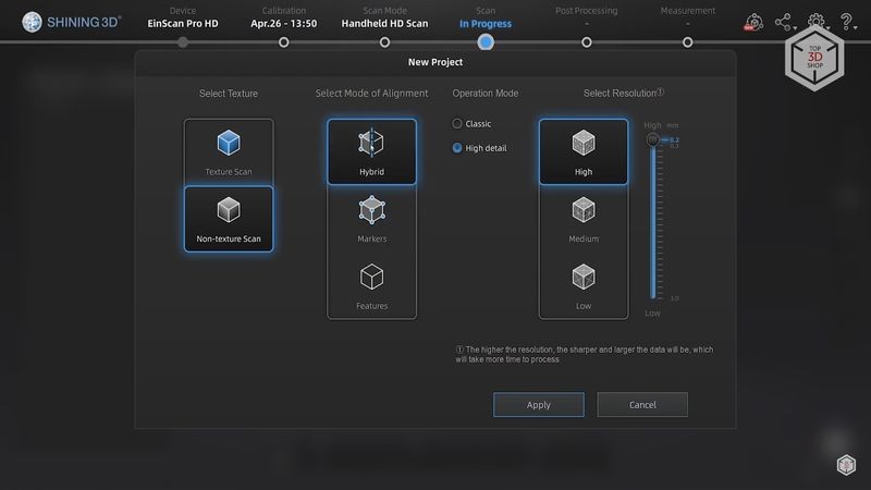
So, let’s check the interface. A list of all the previously saved scans appears in the center of the main screen. You can name the scan in the upper section, by default the name is set as the current date. The button with three stripes is also present. As we have already seen during the calibration, it can be used to access the settings.
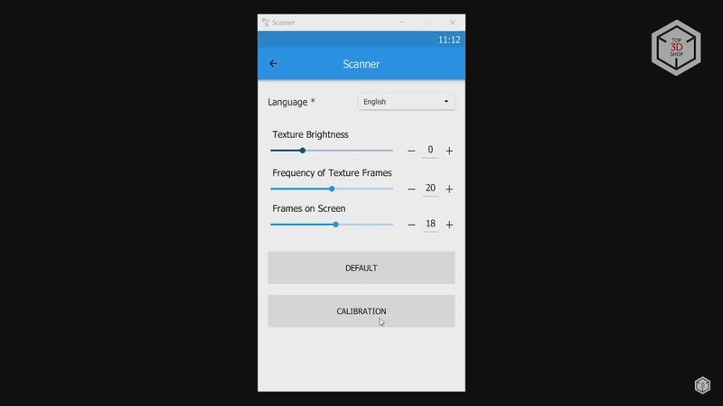
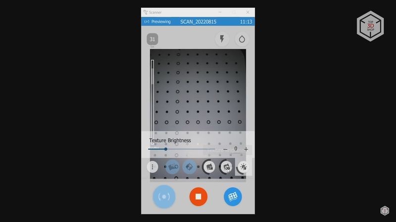
Here you can also choose the language. The next step is to adjust the texture brightness. The number of texture frames determines the frequency with which the texture camera takes shots. If you do not need textures at all, you can set it to zero to save disk space and computing capacity. The next slider controls the screen frames. This setting does not directly affect scanning. It is only responsible for the number of frames displayed on the preview screen during scanning. There is a “Default” button that resets the settings and the “Calibration” button discussed earlier.
The round button in the main menu at the bottom accesses the preview menu. The window is located in the center, and used to ensure that the main parameters are correct, as well as to control the scanning process.
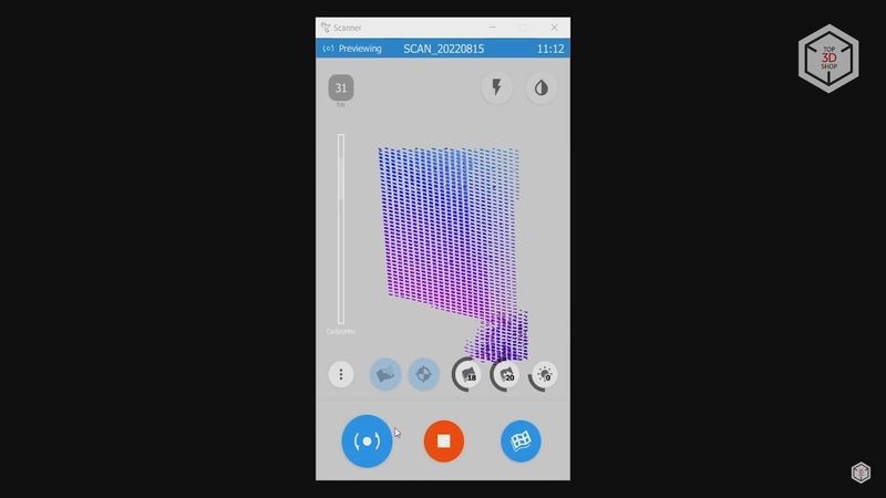
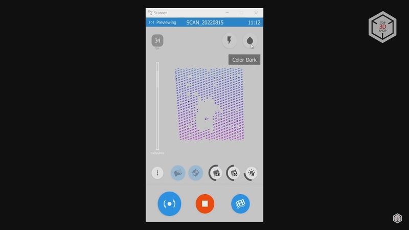
The upper left corner shows the number of frames per second. A lightning bolt icon on the right-hand side is responsible for the flash and has three modes: off, medium and full. The flash is needed to capture better and more uniform textures.
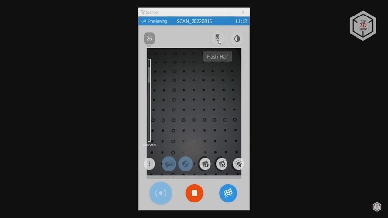
The button in the form of a drop nearby controls the projector’s brightness and has three modes. And this is, perhaps, one of the most important scanning parameters. For dark and black objects, you need to use maximum brightness, indicated by the drop button being completely filled, since black objects absorb the light of the projector. For bright and white objects, the drop should not be fully filled, so that excess light does not reflect from the object and generate noise. There is also an average value with the drop half-filled.
There are also several buttons below the preview screen. The three buttons on the right manage the same options that we have already seen in the settings menu.
Next is the calibration check button, and the Live3D mode that generates and displays a preliminary 3D model on the screen during the scanning process. The button with the three dots is used to adjust the same three parameters: textures brightness, texture frames and preview screen frames.
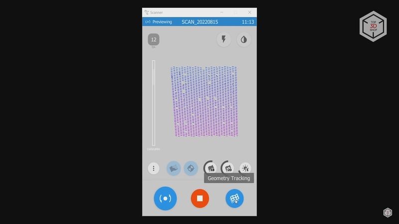
Another very important parameter is located in the bottom right corner. It manages the object’s features used for tracking — there are three of them. Geometry tracking means that Calibry will be guided by the specific features of the object’s geometry during scanning, such as holes, curves, protrusions, and so on. Individual frames will be combined using these features, forming an integral point cloud.
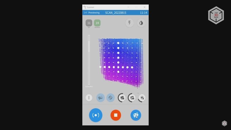
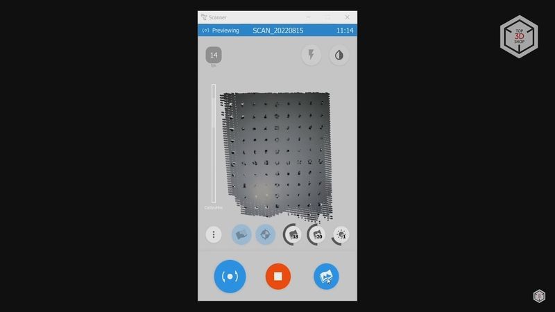
The second type is tracking by markers. In this case, special markers that we saw when unpacking should be placed on or around the object, and the device will use these markers as a reference when scanning.
And the last type of tracking engages textures. If the object has vivid image designs or patterns, the scanner will use them to match the frames.
Here it is worth noting that there is no tracking mode that combines the first two as with Shining 3D scanners, for example. Such a mode enables tracking based on the markers, but when markers are not enough to keep the tracking going, the device switches to geometry mode and continues scanning.
Calibry is not capable of doing this, and if it loses sight of the markers, the scan immediately stops. It would be nice if such hybrid tracking was added in the next firmware and software updates.
Now that we’ve covered the interface and basic settings, let’s move on to the first test scan.
For this figurine, we engaged textures, set the projector’s brightness to medium, and tuned on geometry tracking. The figurine is placed on the turntable with the scanner aiming from a distance of 180 to 300 mm.
The preview window helps to navigate through what the scanner is currently capturing. If the area is too close, it turns yellow, and then red. Areas that are too far away from the scanner turn blue. The best results are generated when the scanner captures details in the green zone, since it provides for a better focus.
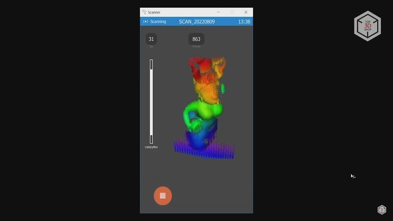
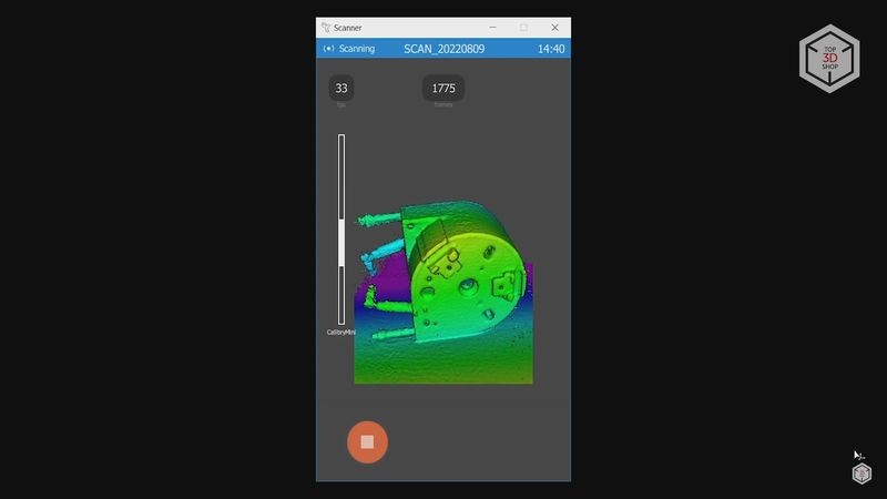
The first scan was done with the Live3D feature turned on. As you can see, only a fraction of the frames are displayed on the screen at a single moment, and this number of frames was dialed in the screen frames setting. We could continue scanning in this mode, of course, but it is quite difficult to monitor the scan progress and understand which areas have been captured.
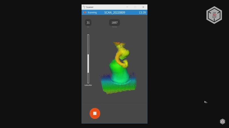
Therefore, we went the easy route and turned Live3D on. In this mode, Calibry immediately displays a preliminary 3D model, highlighting the areas that have been captured and the areas that still need to be scanned. The necessary data is gathered by smoothly moving the scanner in front of the object at the appropriate distance.
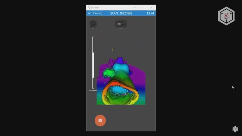
Since we are scanning with a turntable, there is no need to walk around the object. The object is rotated on the table’s platform by hand, allowing the device to capture the geometry from all sides. The only thing to keep an eye on is that the hand should not get into the camera’s field of view and generate noise and unnecessary geometry in the scan. You need to tilt and turn the scanner at different angles to capture the surfaces in the holes and dents.
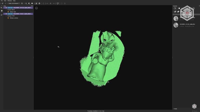
The whole process of scanning the figure in a standing position from all sides took about 2–3 minutes. In general, this is enough to get a decent 3D model, but just in case, we decided to scan the figure also in a lying position in order to capture the geometry from below. The figurine is hollow and we managed to get parts of the inner surface. Naturally, not all of it, since light cannot cover the entirety of the inner surface.
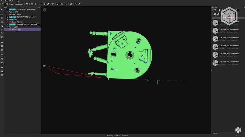
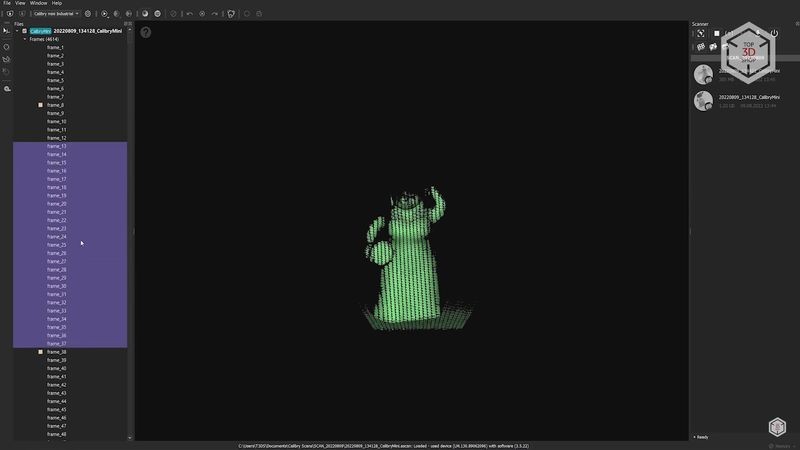
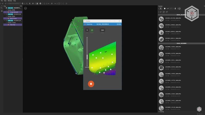
After scanning, we went to the computer to process the data. The list of all the saved scans appears on the right side of the screen. Starting with the first one, we see a simplified point cloud in the central window.
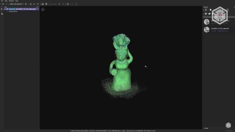
On the left, you can expand the Frames tab with all the individual scans. In our case, there are 4614 of them. Each scan is a small point cloud. Together, they form a complete model. Scans can be selected in groups, deleted if necessary, and groups of frames can be divided into individual projects. As you can see, there is quite a lot of noise, but this should not be an issue since this is a preliminary point cloud.
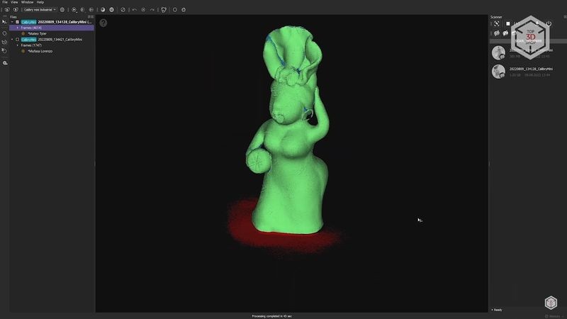
In order to get the final 3D model, we need to go through two main steps: registration and finalization. When registering, the program will align individual scans with each other. And finalization will create a comprehensive 3D model from the point cloud. Click the gear icon, located on top, to configure these processes.
There is only one parameter in the Registration section called “Preliminary cleaning”. It will remove unnecessary noise from the scan. This option should be enabled in most of the scanning sessions, except for scanning hair or extremely small details.

The “Finalization” section offers much more parameters. Resolution is responsible for the details on the final model. The value here can be set as deemed fit, up to one hundredth of a millimeter. But this is not advisable, since it will drastically increase the processing time, and result in a flawed scan. The minimum allowed resolution for this scanner is 0.15 mm. But in most cases, a resolution of 0.2–0.3 mm is enough.
The “Hole filling” option is obviously needed to automatically fill in the holes that result from insufficient coverage of some of the object’s geometry. You can fill all the holes at once, select the maximum radius of the holes that will be automatically filled, or refrain from hole filling at all.

Next comes the “Sharpness” slider. A smaller sharpness value will create a smoother model. At the same time, increasing the sharpness brings out the defects on even surfaces. When scanning with markers, one also employs the “Remove markers” function. We will see how it works later, since we do not have markers in this scanning session.

Filtering by size allows you to automatically remove unattached areas from the scans. You can either remove all of them except for the largest part, or set the maximum number of polygons for the parts that need to be removed.
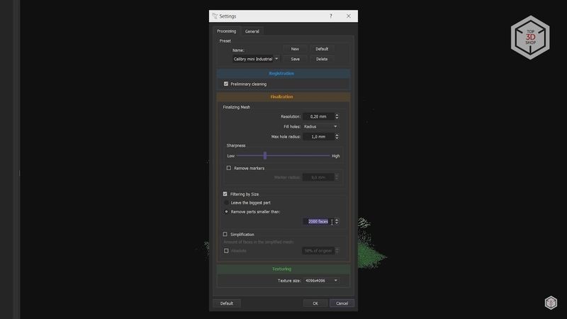
The last finalization parameter is “Simplification”. Scanned models can have extensive numbers of polygons, which require high computing capacity to process, making the processing of such models problematic. With this function, you can simplify the model to a specified value, expressed in the maximum number of polygons or as a percentage of their total number.
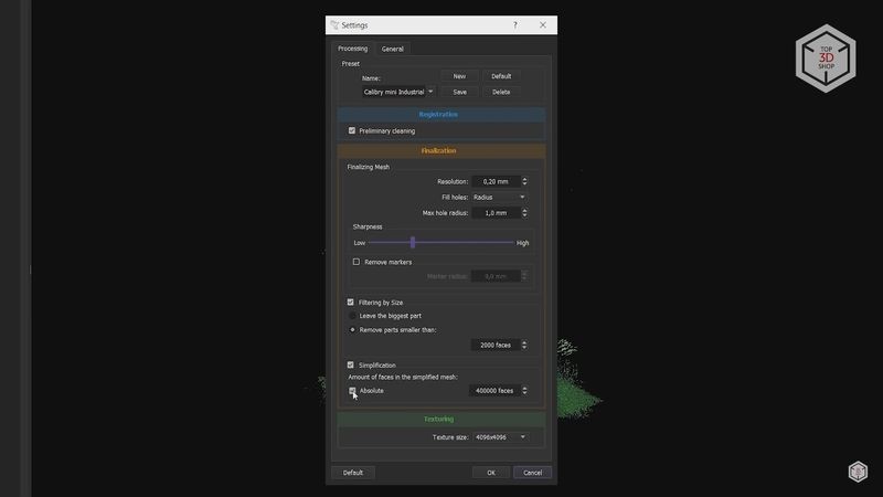
The last section is responsible for the model’s textures. Here you can only select the texture frames resolution. Again, you can leave the maximum value if the computer is powerful enough.
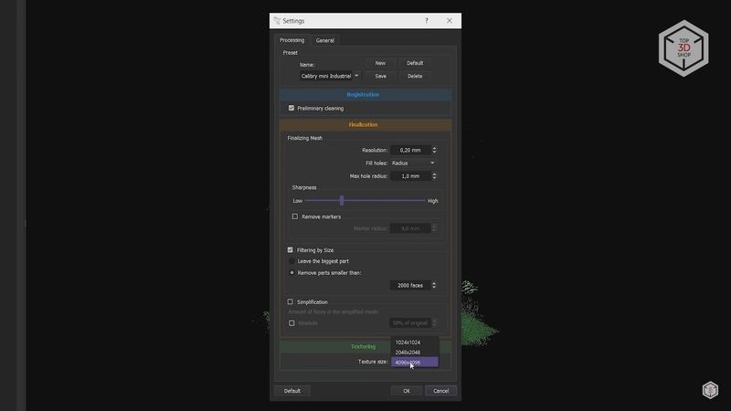
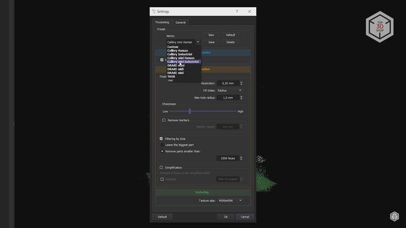
There is a certain number of ready-made presets for all these parameters. Calibry Mini has two of them: Human and Industrial. It is possible to create and save your own presets, as well as reset the settings to their original values.
You can start the registration and finalization of the model by clicking on the button with the Play symbol on top or using the F5 hotkey. You can run these processes individually with a right mouse button click.
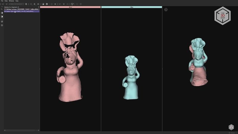
A minute after starting registration, we see that the point cloud began to look much neater and cleaner. All scans matched perfectly, and extra noise was removed. We performed the same procedure with the second scan, where the figurine was lying on the table.
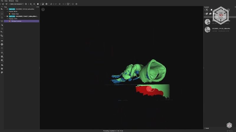
These two scans are not aligned with each other, and in order to do this, you need to launch the initial finalization. Since it will not be the final project, we changed the resolution from 0.2 to 0.3 mm to save time.
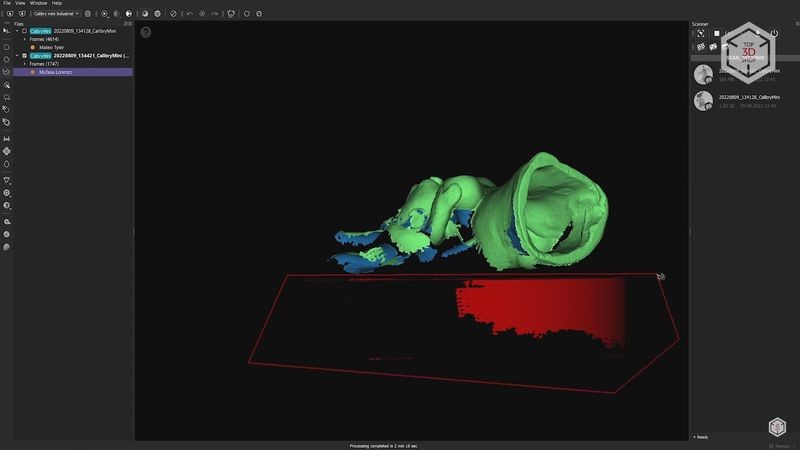
The finalization of these two separate scans took about two minutes. As you can see, the scanner captured the turntable’s geometry along with the figurine, and this data can interfere during alignment, so it is advisable to delete it.
There are several tools on the left-hand side that allow selecting unnecessary areas in different ways. Hold down the Ctrl key to cancel the selection. We selected the excess geometry on both of the scans and pressed the “Delete” button on the keyboard.
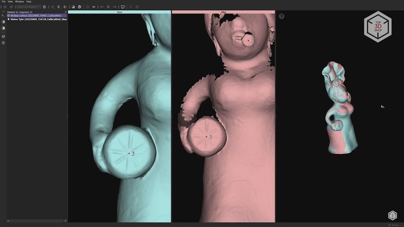
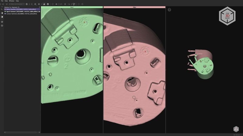
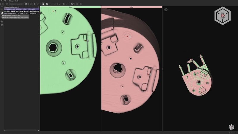
Now we need to align these two scans with respect to each other. Select the two resulting 3D models by holding down the Ctrl key. The “Align by points” button will appear on the left, giving access to the alignment menu.
The left window contains the scan that will be used as a reference for alignment. The center window displays the scan that will be aligned. The result of this alignment is shown in the window on the right. It is always advisable to choose the most complete model as a reference for alignment, by right-clicking on the corresponding scan and selecting “Set base”.
Now it’s necessary to highlight the common points for both models with a minimum of three points. Highest accuracy is not required at this stage, but the precision of the selected common points will generate a more uniform and accurate scan alignment.
The next step is the so-called multiple registration and finalization. The main difference is that in this case individual frames from both scans will be aligned based on the points selected earlier. Click on the button next to the pre-registration button and start the multiple registration.
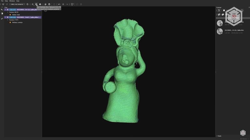
The two resulting scans already look much more uniform. Although we removed the extra parts from the finalized models, they are still present in the point clouds. Oddly enough, these extra points contribute to better alignment during the multiple registration process. But now they can be removed from the point cloud, since we will no longer need them.
The procedure is similar to what we have done before, and here we change the resolution to the desired value, in our case 0.2 mm.
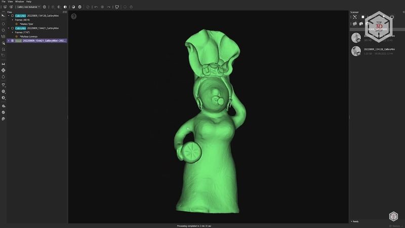
Now, let’s launch the multiple finalization. After 2.5 minutes we are presented with the final 3D model.
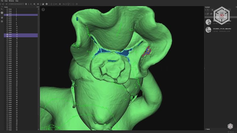
We did not enable automatic hole filling, which resulted in some missing geometry. There is a special function for manual hole filling, used for closing off the selected holes individually or filling all the holes at once. For complex holes, you can use a function that creates small bridges that divide the holes into parts. There is also a tool for smoothing the surfaces, optimizing the polygonal mesh, simplifying the model and special measurement tools.
The last step in this scan is to apply textures. Click on the button that comes immediately after multiple registration and finalization. After 6 minutes of processing, we got the finished model with textures.
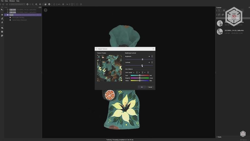
There are also several tools for editing the textures, such as adjusting brightness, contrast, and colors. You can make areas brighter or remove specific texture areas with auto-filling, based on the surrounding pattern.
The model turned out to be of decent quality and suitable for further use. You can export the model to one of the popular 3D formats. The OBJ format is usually used for textured 3D models.
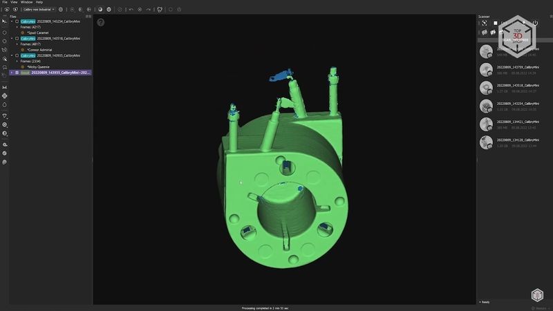
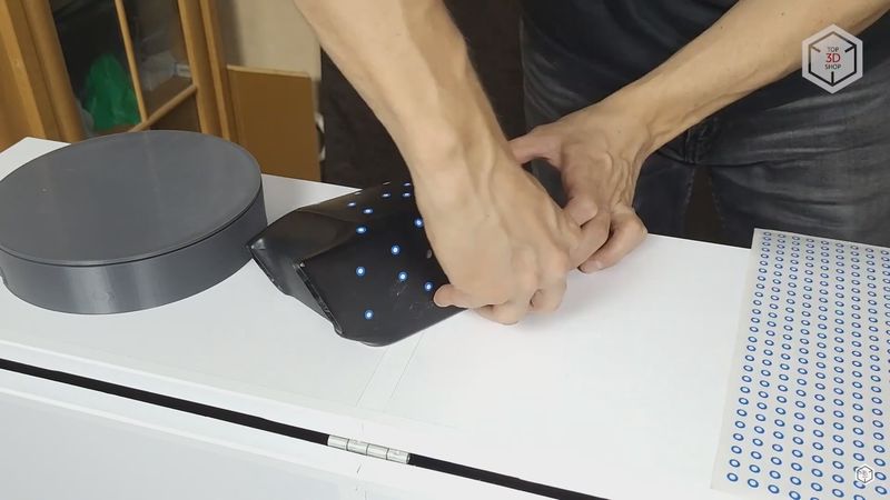
For the second test, we chose a technical part. This is a small heating element from a coffee machine. It has a rather complex shape with a large number of fasteners, holes, and cavities.
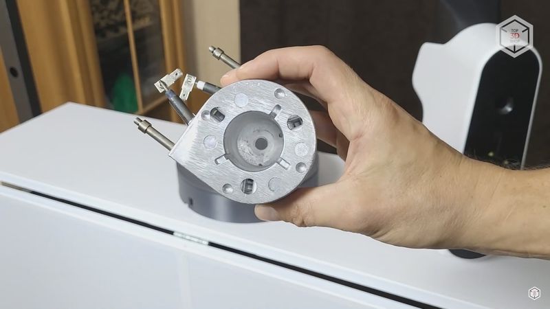
We used the same scanning settings as for the figurine model except that the Texture Frame Rate was set to zero, since we will not be needing textures in this scan.
The heater was carefully scanned from two sides in an upward position, with much effort devoted to covering as many holes and cavities as possible. And just in case, we made another intermediate scan with the heating element lying on its side.
Thanks to the large amount of details and geometry features, there were no difficulties with tracking. Individual scans alignment was also quite successful. This is where a feature that we did not use in the first scan came in handy.
In the case of three or more scans, after aligning two of them, you can click the “Add Aligned to Base” button. In this case, the two scans will merge into one, and aligning subsequent scans will be much easier due to the larger number of details. Otherwise, the procedure was not much different from the first test-scan.
As a result, we got a fairly accurate and detailed 3D model. Remarkably, the Calibry Mini was able to capture even the shiny steel connectors. Not completely, but as a rule, most scanners do not even register such details without special matting spray coating.
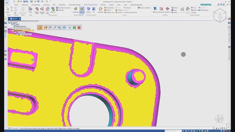
Few holes are still present on the model, but as a rule, it is not necessary to fill them in when processing scans of technical parts. In most cases, such scans are not final and are used as reference models that help in the creation of comprehensive parametric 3D models, which can be used for production or 3D printing. Usually, this process is done with special software such as Geomagic Design or Solid Edge.
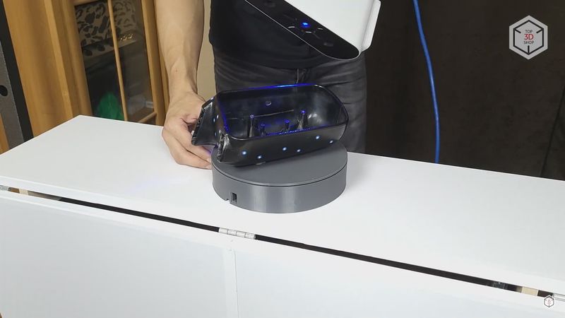
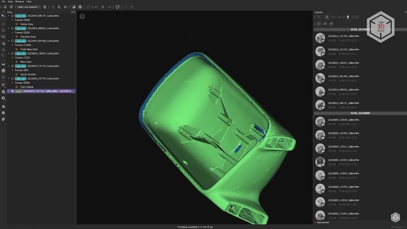
For the next test, we took a side rear-view mirror from a 1992 Saab 9000. The mirror consists of several parts with moving mechanisms inside, an electric drive, and so on.
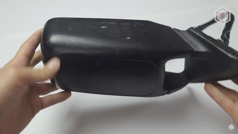
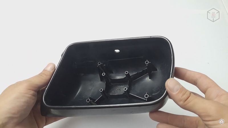
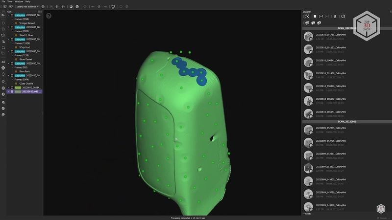
There is no point in scanning it in its entirety. So we took it apart and tried to scan only the main plastic housing. Since it is made of black plastic, we set the mode for scanning dark objects in the scanner settings. The exterior of the part has very little pronounced details, so we decided to use scanning with markers.
The markers were glued to the model close enough to each other in a random order so that each individual frame captures at least three markers or more. The number of markers in view is displayed next to frames per second. The scan immediately pauses when the scanner loses the track.
A strange aspect was noticed during scanning with markers. It would seem that geometry-based computing and alignment should be more difficult to process. But for some reason the scanner captured significantly fewer frames per second in marker tracking mode compared to the geometry-based one. As a result, such scans took longer and the process was slower. Geometry-based tracking produced less data and we had to rescan some areas several times, since in the processing stage, it turned out that some areas were not scanned well enough.
Since the inner side of the mirror contains fasteners, we used geometry-based tracking for scanning this particular side.
Aligning the internal and external geometry scans experienced no issues. In this test, we used a rather useful function for pre-finalization and multiple finalization. Instead of removing the unnecessary geometry, such as the turntable, we enabled Priority Mode, selected the parts we needed, and set them as the Main Object. The extra parts disappeared from the view window and stopped interfering with the process. However, these parts will still be taken into account during scans finalization. This function turned out to be very convenient.
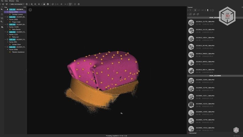
As a result, we captured the majority of the mirror’s geometry. Of course, there are areas that could not be captured, but the data received was quite enough for further use.
The only thing that confused us was that the markers had left small bulges on the surface. At the same time, the markers automatic removal function does not eliminate the markers only, but also cuts through the model’s surface. The holes resulting in this case are very hard to fill in, greatly distorting the geometry of the model. Of course, you can leave these holes, and they should not interfere much when remodeling, or you can manually select the marker protrusions, delete them, and fill in the holes individually. The markers’ automatic removal function seems to need improvement, since it is inconvenient to use in its current state.
For the last test, we went with scanning a human ear and hand. The manufacturer claims that the Calibry Mini’s blue light is very efficient in scanning human skin. And scanning individual parts of the body can be very useful for medical applications.
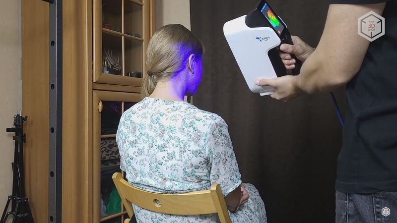
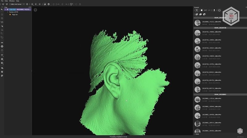
There were no significant difficulties in scanning the ear. Except that it turned out to be almost impossible to scan the back side since it is too close to the head and hard for the scanner’s light to reach.
Some areas inside the ear were also hard to scan. However, the Calibry Mini was able to capture hair with no difficulty. The projected light did not get caught in the hair and the camera was able to capture it efficiently.
The situation was a little more complicated when scanning the hand, although there were no areas that could not get covered. The main difficulty was keeping the hand absolutely still throughout the entire scan. No matter how hard we tried, the fingers sometimes trembled, affecting the final result in a negative way. Of course, you can scan a hand from one side while placed on the table, but it is simply impossible to scan it from the other side without changing the fingers’ articulation.
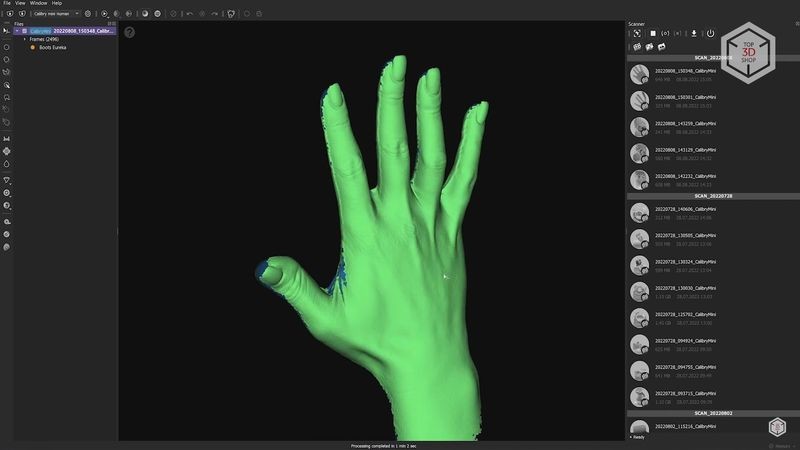
Roughly speaking, it is possible to scan a hand, and it is a simple process for the person operating the scanner. But the person scanned must have a good deal of self-possession to hold the limb still.
Overall, we are definitely satisfied with the Thor3D Calibry Mini scanner. First, it is convenient to use, especially thanks to the built-in touch screen. Secondly, the quality of the resulting scans is decent and fully complies with the declared capabilities. We were pleasantly surprised by the quality of scanning black and shiny objects, and we never had to resort to using a special matting spray. Also, the scanner performed well when scanning human skin and hair.
The Calibry Nest software did not feel user-friendly at first, but after getting used to it, we found a lot of thought-through and time-saving features. Undoubtedly, there still is room for perfection, but knowing how the Calibry Nest has been updated and improved before, there is hope that all the missing tools will be added over time.

Update your browser to view this website correctly. Update my browser now


Write a comment