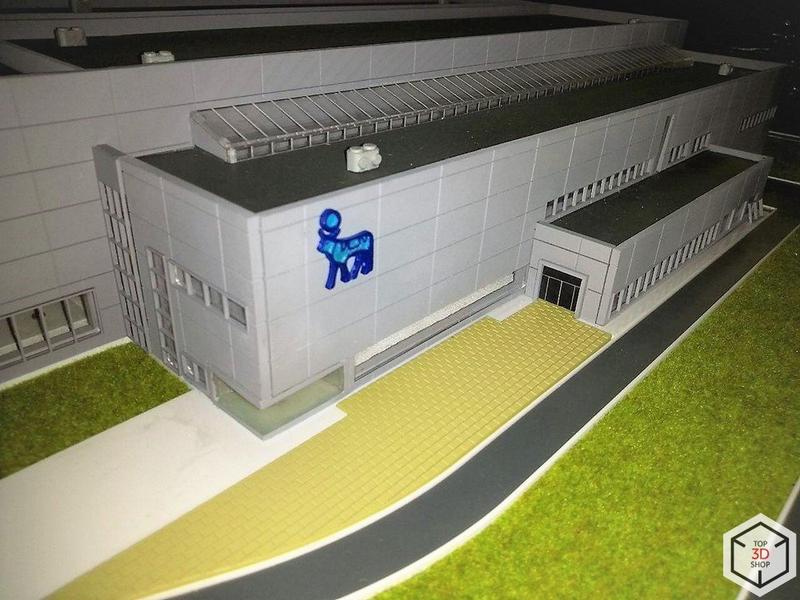
In this article, we show how we created a scale model of the head office building of Novo Nordisk, a global pharmaceutical company.
The popularity of 3D printing in architecture keeps growing. Developers and architects value physical models, and many companies decorate their offices with miniature versions of their buildings. This project is one of those cases.
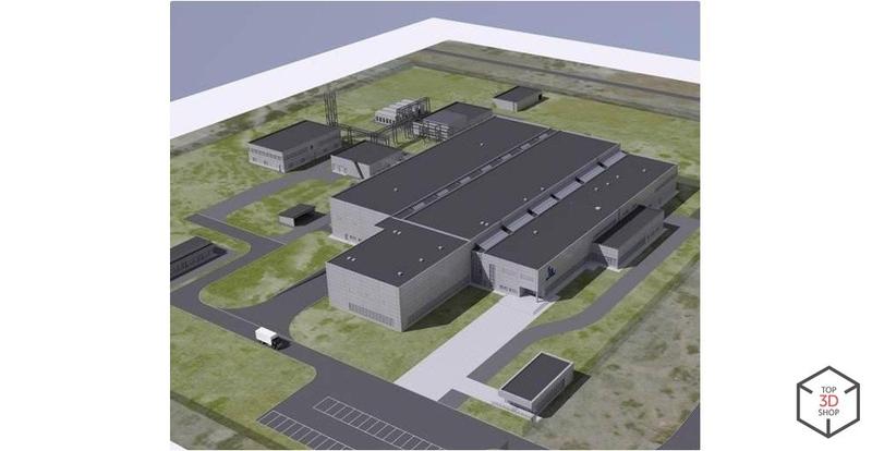
The client sent us:
Predetermined renders of the buildings, structures, and site infrastructure
A layout plan
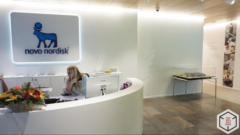
Several photos of the real facility
We couldn’t get the original 3D models used to create the renders. That didn’t cause problems: when we design a physical layout, it’s often more convenient to build our own digital models from scratch and adapt them to the requirements of the mockup.
Before 3D printing and CNC machines, model makers built architectural mockups by hand from paper, foam plastic, and similar materials. That approach had two main weaknesses:
Low dimensional accuracy
Long and labor-intensive production
Digital technologies fix both issues and give much more control over scale, geometry, and detail.
At the start, we had:
A few photos
Several renders
A partial plan of the main building
We spent a lot of time working out the correct scale. We produced several test renders of the base and compared them with the reference images.
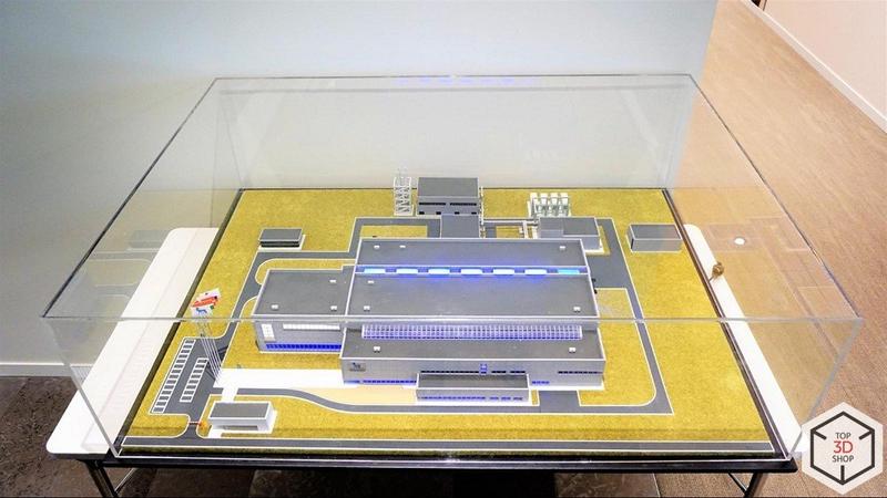
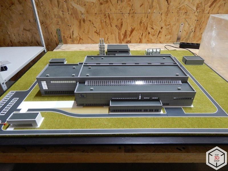
The client set one clear requirement: Place the architectural model on an area of no more than 1 m².
We met that requirement. The base of the model occupies 0.97 m².
During the miniature evaluation stage, we saw that the main building occupied a long, dominant position on the model area. We decided to:
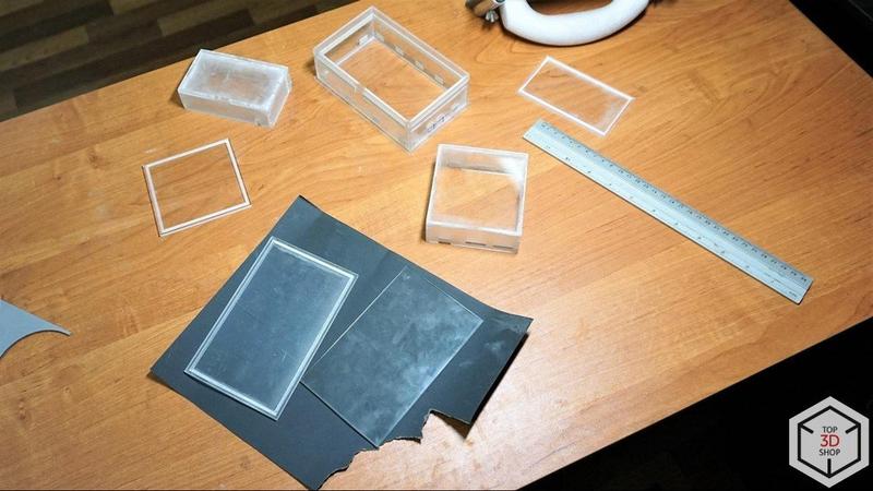
Because all objects in the project had clear shapes and angles, we chose acrylic as the primary material. It offers:
The right level of elasticity (not too brittle, not too flexible)
Clean, sharp edges after shaping and laser cutting
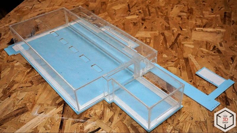
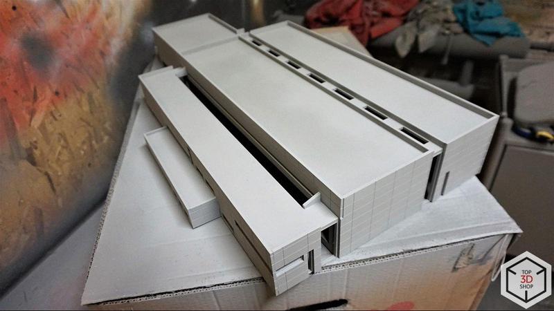
We built the frame of the main building from 4 mm acrylic. This thickness:
Suits the overall model scale
Provides enough rigidity
Remains convenient to cut and assemble
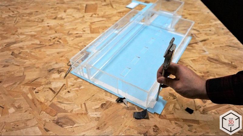
We designed the mockup as a modular construction kit, taking into account:
Dimensional tolerances of 0.1 mm
Laser cut width of 0.13 mm
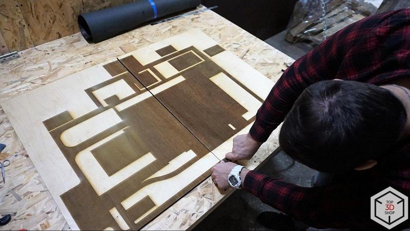
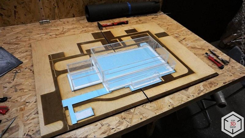
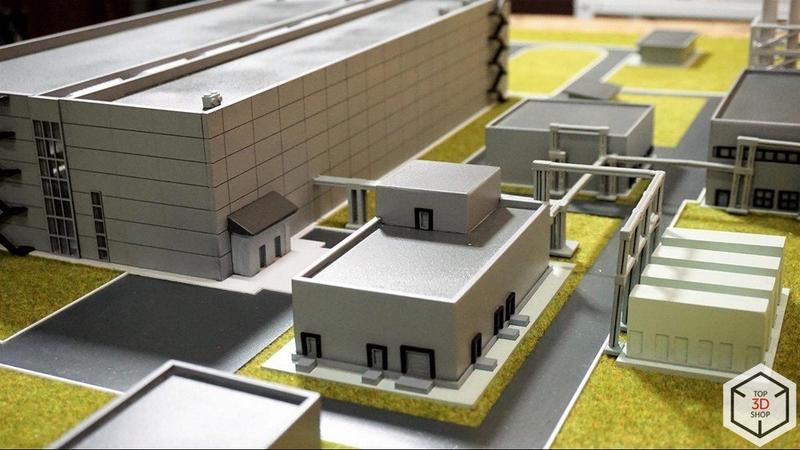
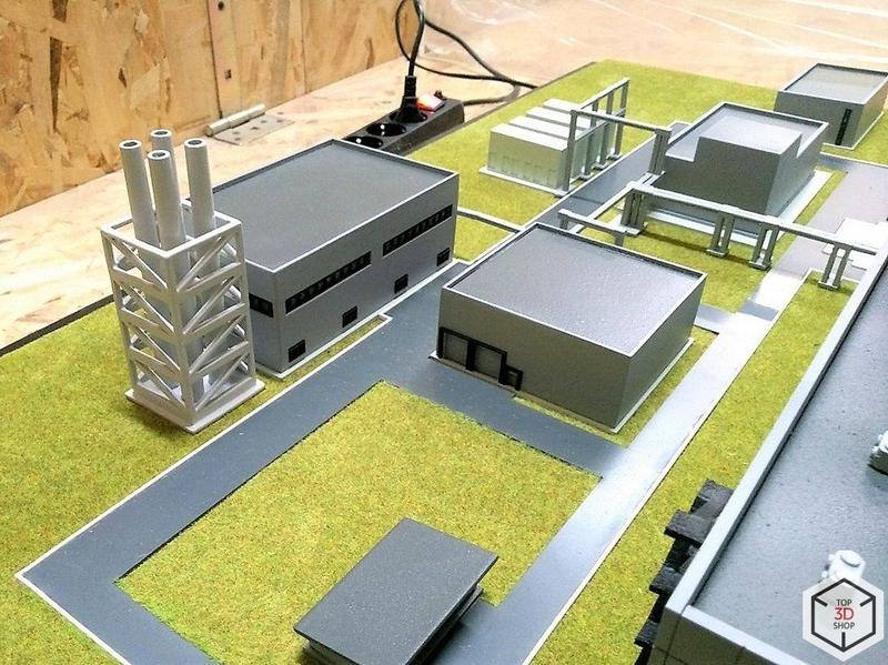
Next, we created the architectural base of the site: paths, building foundations, parking areas, and curbs. We:
Engraved all elements 1 mm deep on 9 mm plywood
Cut out the parts to shape
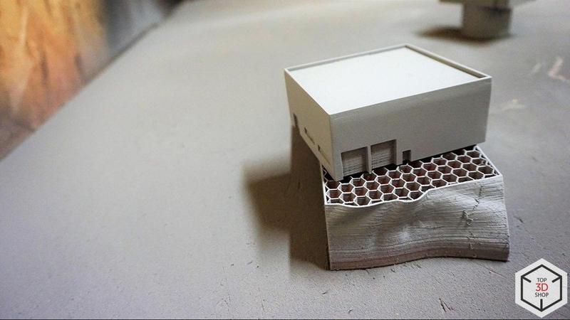
After that, we designed the remaining buildings on the site. About half of them came from sheet materials; the rest we produced on SLA and FDM 3D printers.
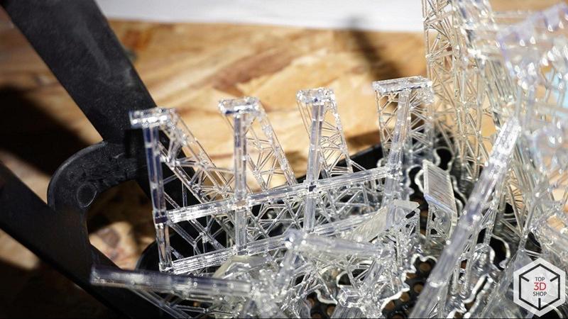
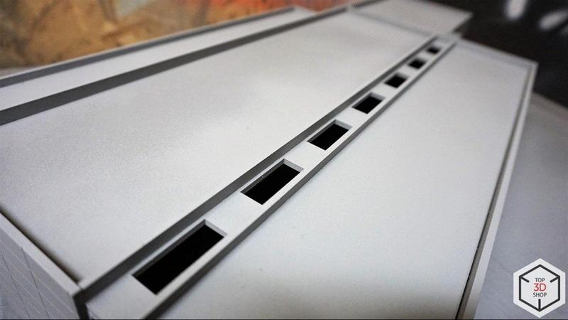
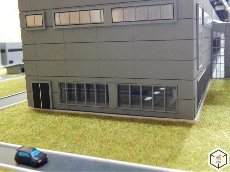
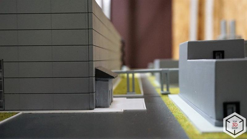
While the model maker assembled, polished, smoothed, and primed the prepared elements, the engineers worked on the cladding for the main building. They chose 3 mm acrylic with a 0.5 mm relief pattern. We cut the windows and doors through the acrylic to match the design.
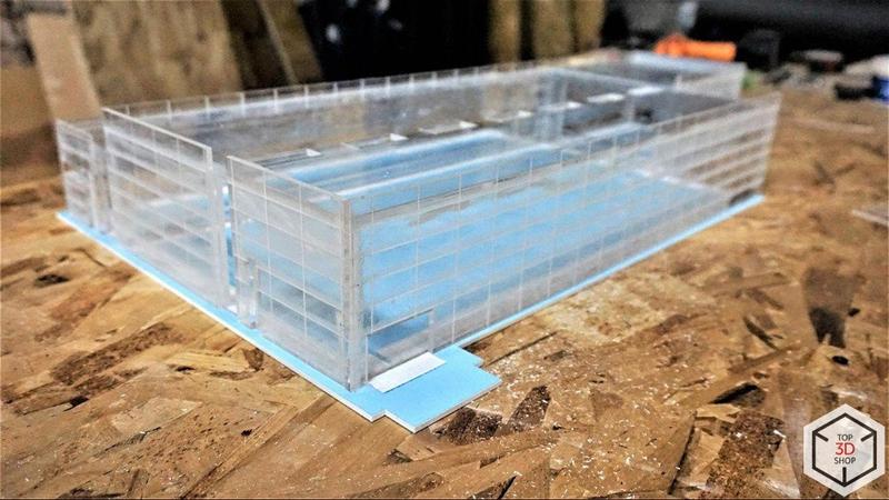
Then we moved to assembly and gluing. All elements fit together as planned. The tolerances we built into the design did their job, and the model went together like a construction kit.
For the base, we used a 15 mm OSB (oriented strand board) board. It provides:
Good stiffness
A stable platform for the model
Better fire behavior compared to many wood-based panels
We then:
Coated the details with putty
Applied primer
Painted the base black
Covered it with four layers of matte lacquer
This finishing sequence ensured that the acrylic parts of the model would not leave marks or scratches on the base surface and that the base would keep a neat appearance over time.
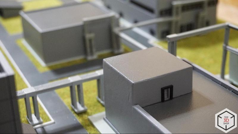
The most visually interesting stage was processing and coloring the buildings.
After assembly, we applied several layers of primer to all elements. Primer preserved the texture and relief of the buildings, but it also revealed surface defects.
We removed these defects using manual mechanical processing with abrasive paper — the classic way. This gave us full control over edges and surfaces.
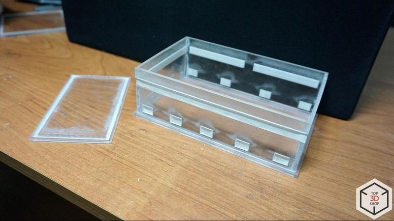
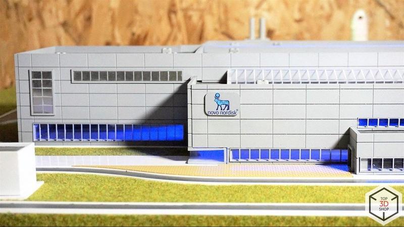
We painted the interiors of the building frames black and then lacquered them. This blocked light bleed-through from the internal lighting, so translucent glow did not appear on the outer walls.
We could have built the frames from black acrylic, but we already had transparent acrylic in the workflow. Painting and lacquering saved time, which mattered because the deadline was tight.
To give the roof a textured surface, we used acrylic polishing dust:
Collected the dust during acrylic polishing
Sprayed it onto the surface during painting
Created a uniform, fine-dispersion coating that imitated roof texture
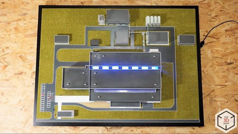
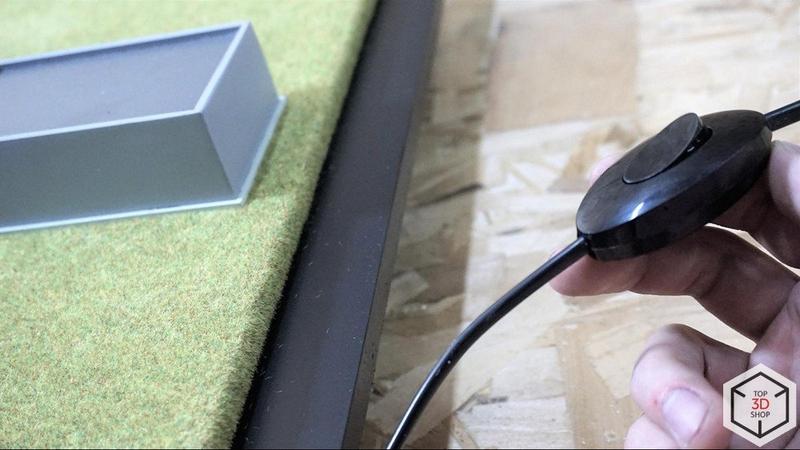
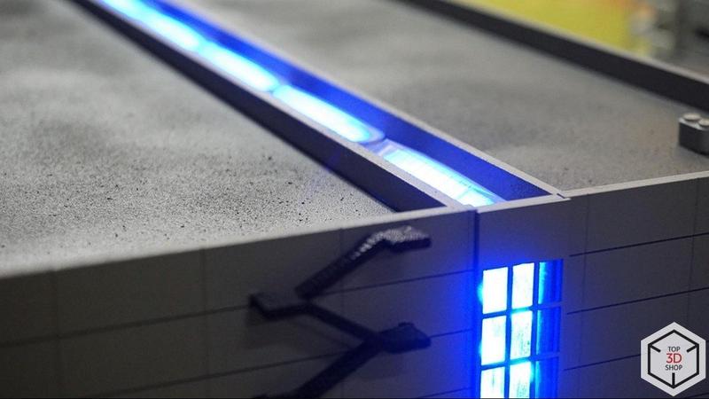
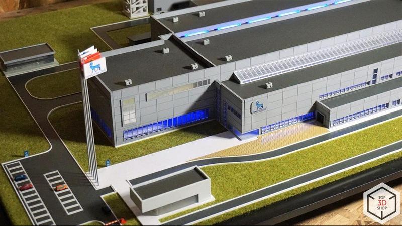
Lighting was a critical part of the project. We needed the model to look alive and realistic.
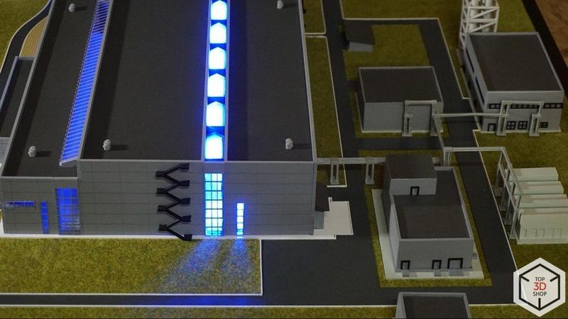
We:
Placed a base plate in the form of a finished block inside the building
Attached an LED strip to that block
Routed the wires through the model base
Mounted the power supply unit on the underside of the base
Using the 15mm oriented strand board for the base helped from a safety standpoint: the board does not ignite easily and does not sustain burning. In case of a fault, the LED system simply stops working instead of causing more serious issues.
We paid special attention to the details.
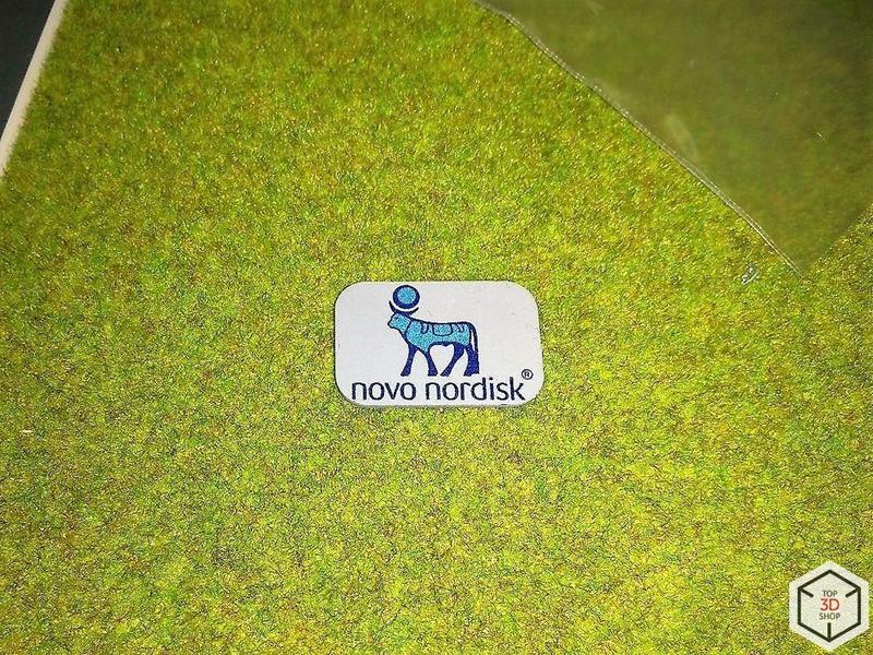
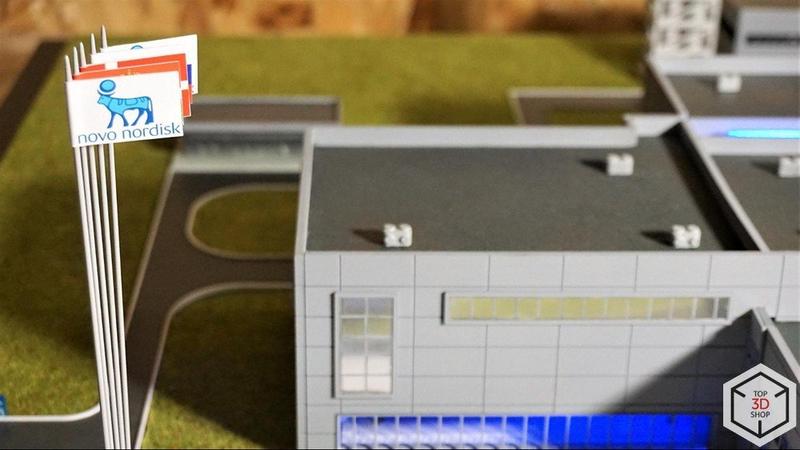
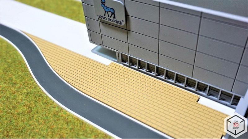
Logo: We created the logo based on the client’s branding, printed it on a Formlabs Form 2 SLA printer, and hand-painted it with a brush. The result did not fully meet our expectations. We then re-created the logo in high resolution and sent it to UV printing, which produced a sharper and more consistent finish.
Cars: We printed the cars with SLA technology and hand-painted them. Buying ready-made cars would have taken more time (search, delivery) and reduced the originality and cohesion of the project. Custom-printed vehicles better matched the model’s style.
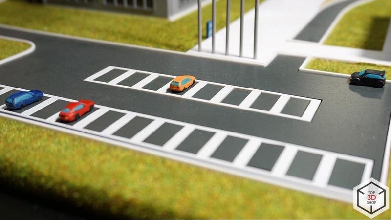
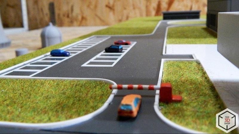
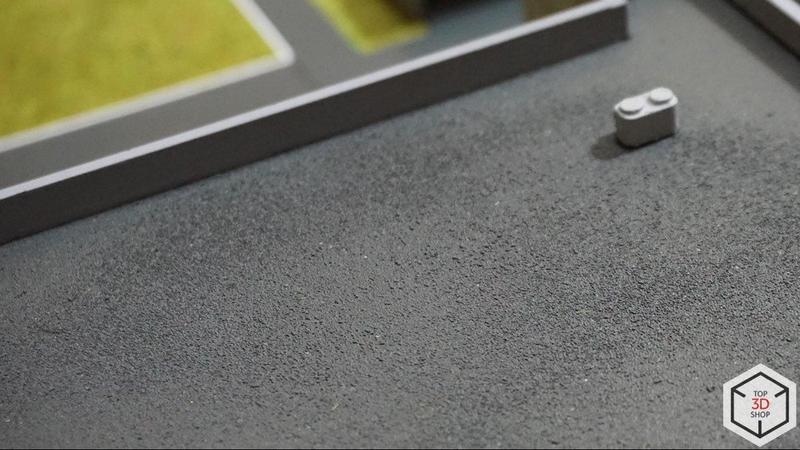
Grass: we applied fiber flock on the base to imitate grass and landscaping around the buildings.
Chimneys: we designed and 3D printed the chimneys, then finished, polished, and painted them.
Flagpoles: We made the flagpoles from steel to keep them stiff and straight. Each flagpole measured 25 cm in length with a 1.5 mm diameter.
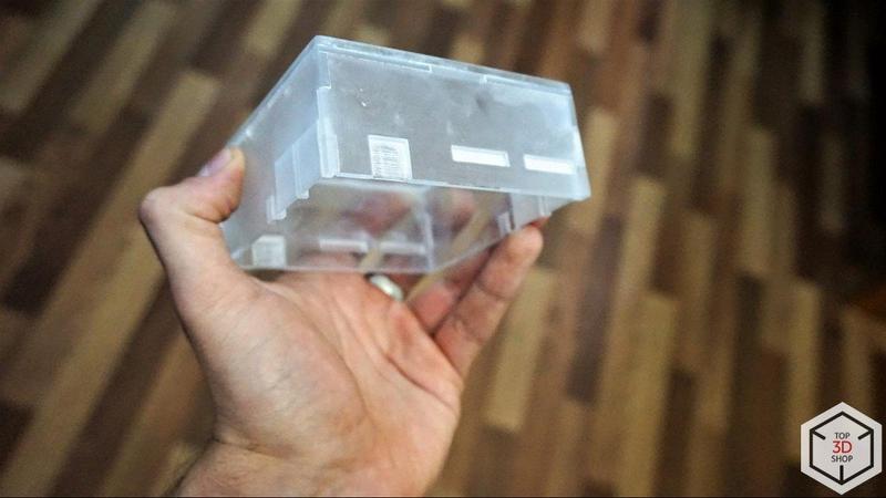
We manufactured the display case from 4 mm acrylic. It is a single piece that covers the entire model.
We mounted the case with small gaps around the perimeter. We prefer to build display covers slightly larger rather than risk tight tolerances that might press on or damage the model.
Near the end of the project, we discovered inconsistent entrance lobby geometry across the provided renders. The client hadn’t supplied clear guidance for that area, and we made our own design decision — a mistake in this context.
During the review, the client pointed out:
The lobby geometry did not match their expectations
A few other minor discrepancies
Together with the client, we:
Documented all issues
Defined specific corrective actions
Agreed on a final delivery date
This experience reinforced the value of detailed, proactive clarification on large projects, especially in visually sensitive areas like main entrances.
On large, complex mockups, we always ask many questions and discuss details with the client. This project confirmed once again that thorough, early clarification directly improves the final result.
You can order a precise 3D model of almost any object, at the quality level you need, by contacting Top3DShop.
If you receive so many architectural and design orders that you are considering in-house production, our specialists will help you buy 3D printers, buy 3D scanners, consumables, and other equipment to build your own 3D printing and prototyping workflow.
Update your browser to view this website correctly. Update my browser now
Write a comment