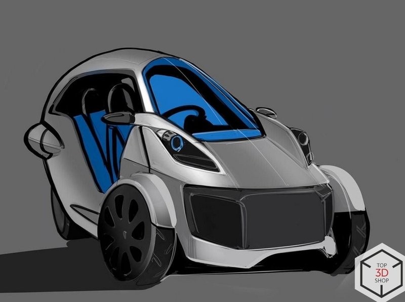
We 3D scanned an electric car for EVTech, an electric vehicle manufacturer. They needed accurate geometry to revise the design and plan upgrades to the body, hood, and fenders. The updated parts would be produced by rotational molding and automatic vacuum forming, so we chose stationary structured-light 3D scanning for high accuracy and detail.
The project was urgent: we had to scan the car, refine the body and internals, and deliver data that simplified component placement and enabled design changes.
Preparation
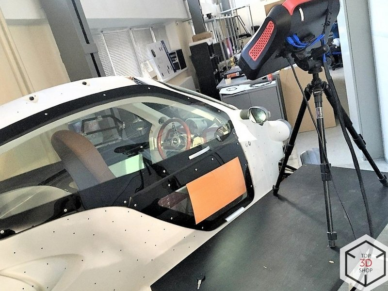
Scanning the car with a stationary structured-light 3D scanner
Processing and merging the data into a single digital model
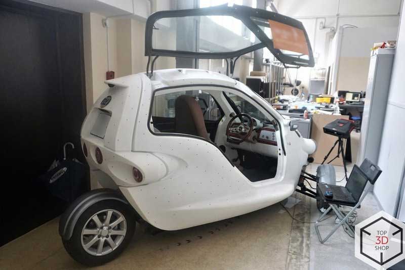
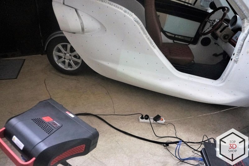
We moved the car into our Service Department workshop. Preparation took about 30 minutes:
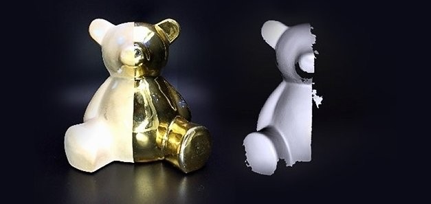
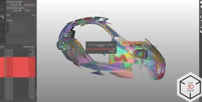
We covered reflective and glossy surfaces to prevent glare. Uncontrolled reflections cause scan defects like holes and black spots in the data. See the example below.
We applied reference markers to the body to create a point grid. The scanner uses these markers to calculate point coordinates and track its position.
We installed the equipment and calibration board so we could quickly recalibrate, if we moved the scanner.
We placed the markers in a random pattern so their relative positions were always unique. This helped the scanner align frames correctly and reconstruct the surface shape more reliably.
Stage 1. Capturing the Basic Geometry

Picture 1.1 Side surface of the car.
Picture 1.2 Side surface of the car.
We started with the side surface of the car, since it is the largest continuous area (picture 1). This first scan let us spot and solve issues early.
One of the first problems was file size.
Our laptop (Intel Core i7 CPU and GeForce GTX 960M GPU) couldn’t merge and save projects with more than 150,000 points. The software crashed or failed when we tried to process larger point clouds.
To fix this, we used the scanner software’s automatic simplifying function:
We scanned and automatically aligned the surfaces in the same program.
We reduced point density during processing so the laptop could handle the data.
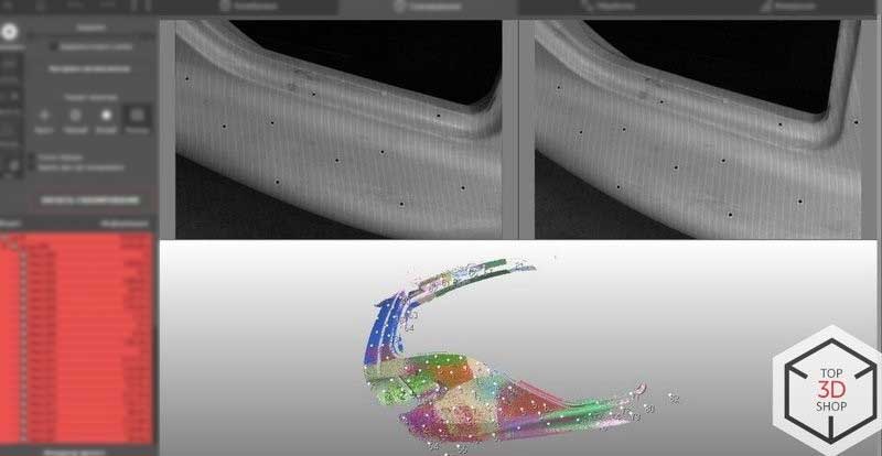
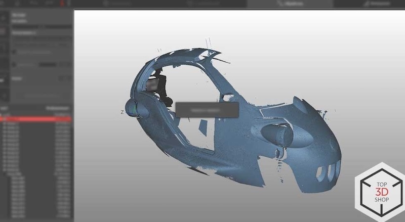
Picture 2. Point cloud of the side surface.
Picture 3. The surface we ended up with after scanning the rear side.
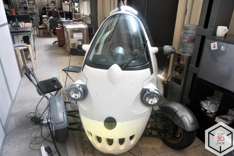
By moving the scanner, we captured the geometry of the front side of the car (picture 4).
.jpg)
Picture 4.
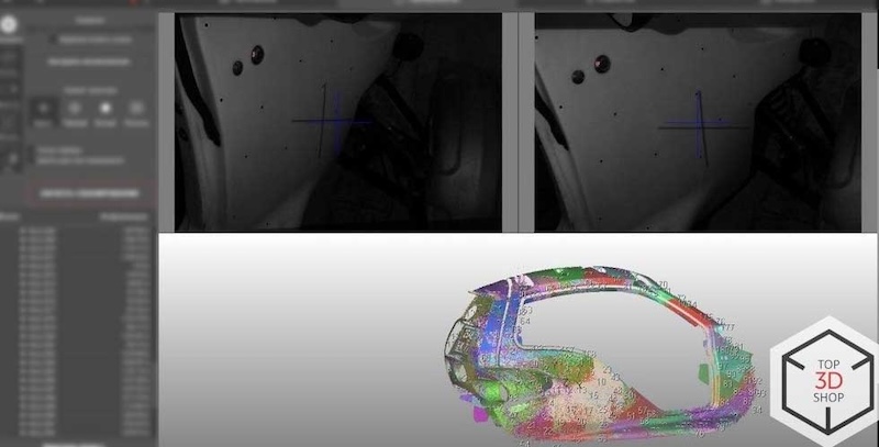
The next thing to do was to scan headlights, rocker panels, and the edges of door frames — everything that can be easily removed without using a tire jack or a repair pit. You can observe the results in pictures 5, 6, and 7. In picture 7 you can see the result of aligning all of the frames into a single model.
.jpg)
Picture 5.
Picture 6.
Picture 7.
Stage 2. Processing the Point Cloud and Building the Model
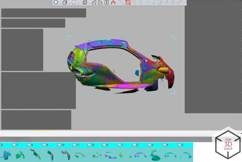
Picture 8. 13 .stl files uploaded from a scanner.
The complete scan reached about 500 million points, which was too heavy to handle as a single project. The software couldn’t import that much data at once.
We solved this by:
Saving the scan in 13 separate .stl files
Importing these parts and merging them into one polygonal grid
Since the car is symmetrical, we used the Mirror function to reconstruct the missing half and complete the geometry faster.
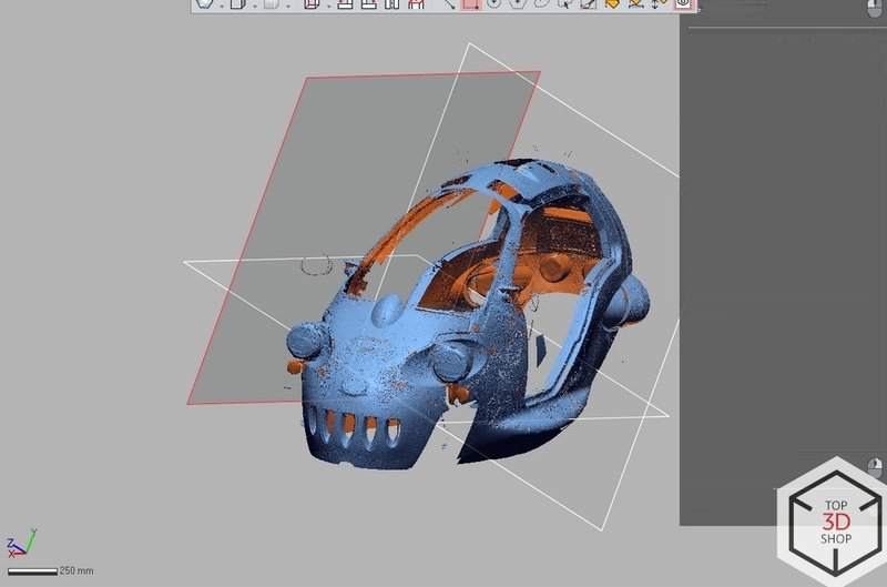
The hardest part was getting rid of scanning defects.
Many raw scans had defects: holes, black areas, and missing data. The root cause wasn’t the scanner itself, but:
Lags and crashes in the software
A USB hub between the cameras and the laptop, which created instability
Connect the scanner directly to a PC, without a USB hub.
Use a machine with at least 24 GB of RAM for comfortable work with large objects.
The scanner package includes a mini-computer, which works well for small objects, but large projects like a full car body need a more powerful workstation.
In our case, we:
Re-scanned problem areas
Aligned the new data with the existing model to patch defects
Our Service Department also recommends using handheld 3D scanners for large objects (over 1 meter in any dimension). Handheld systems handle big surfaces more easily. We chose a stationary structured-light scanner for this job because of its high accuracy, which was overkill for large body panels but very helpful for mechanical components.
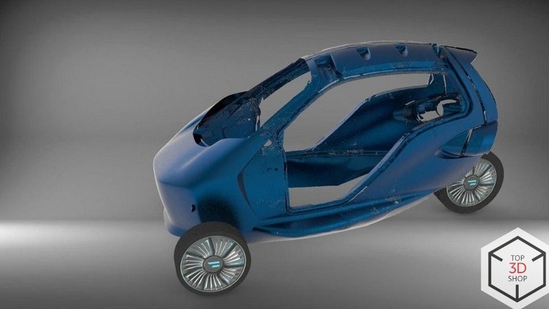
The final digital model turned out very accurate: the deviation from the original car did not exceed 0.2 mm.
We can confidently recommend structured-light 3D scanning for engineering tasks such as:
R&D of car and motorcycle body parts
Hull and bodywork design for small boats and motorboats
Modding, customization, and repair where precise geometry matters
Buy 3D scanners from Top3DShop to get the best training, support and after-sales service.
Update your browser to view this website correctly. Update my browser now
Write a comment