Hello everyone!
In this article we’ll show you how a simple enthusiast can craft a functional Ultimaker 3D printer. This piece is based on the research and work of one of 3D printing enthusiasts. We will describe the assembly process in details — from ordering of components to the assembly process itself, programming and the rest. Of course, we will include pictures so you don’t get confused.
Cost: the printer is going to cost you roughly $400-500 — it’ll be a reliable and high-quality machine.
There are several reasons:
Ultimaker was chosen as the basis of the printer we’re going to craft:
3 mm – Pros:
3 mm – Cons:
1.75 mm – Pros:
1.75 mm – Cons:
So, here we go! The article will consist of the following parts:
1. Buying all the necessary supplies.
2. Assembly of the printer. Frame and mechanical components.
3. Assembly of the printer. Electronics.
4. Firmware and calibration.
Required components:
1. Frame made of any 6 mm thick sheet material (plywood, MDF, acryl, monolithic polycarbonate, etc.).
A plywood case costs approximately $18-31.
If anyone has doubts concerning the usability of a plywood case, don’t be afraid, it’ll do just fine.
2. Aluminum bed base – various costs starting at $11; Plywood is also an option, but not everyone likes it. There are some drawing schemes of the bed: LM12LUU with an adapter is required instead of LMK12LUU, or, alternatively, another kind of bearing is required for the trapezoidal screw.
3. 4 mm glass can be ordered from any glass studio – $1.55-1.85, here’s the drawing scheme.
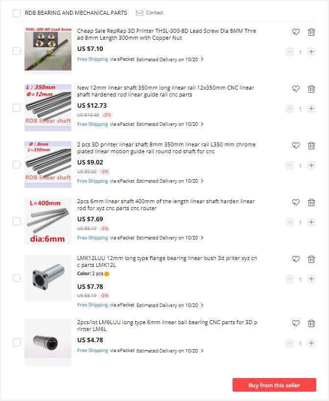
4. LM6LUU – 2 pcs. – $4.78.
5. LMK12LUU - 2 pcs. - $7.78.
6. Bearings F688 - 8 pcs. - $3.04 for 10 pcs.
7. Shafts 6 mm - 2 pcs, one 300.5 long and the other 320 mm long, you can either ask the seller to cut off a piece of particular length or cut it yourself - $7.69.
8. Shafts 8 mm - 4 pcs, two 348 mm-long and the other two 337 mm-long, you can either ask the seller to cut off a piece of particular length or cut it yourself - $9.02.
9. Shafts 12 mm - 2 pcs. 339 mm each , you can either ask the seller to cut off a piece of particular length or cut it yourself - $12.73.
10. Pneumatic Connector - 1 pcs. 13.88 for 1.75 or 3 mm.
11. Encoder- 1 pcs. - $0.50.
12. Dual pulley with 20 teeth for 8 mm shafts - $1.98.
13. HeatBed - 1 pcs. - $8,18.
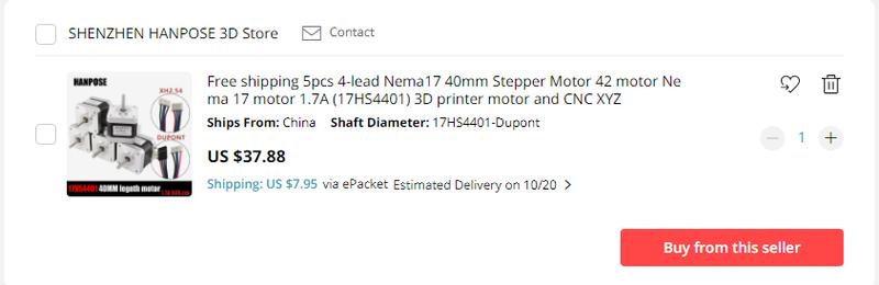
14. Stepper motors - 4 pcs. required (sold in packages of 5 pcs. for 37.88). Trapezoidal screw - $7.10. Couplers - 270 for 5 pcs, can be printed instead.
15. Copper sleeves with graphite inserts, long and short belts and belt springs - 1 package – sold in packages for $12.42 (carriages can be printed; as to the belt, a standard GT2 belt without springs can be used instead - you'll save some money this way).
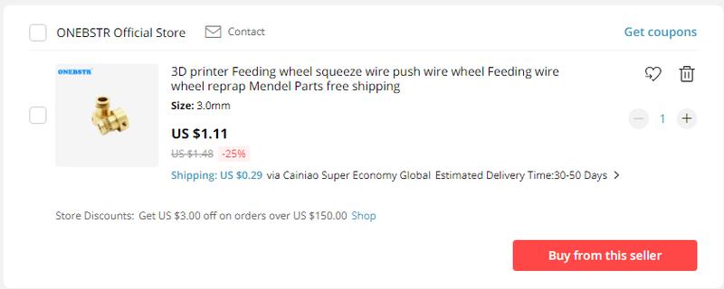
16. Feeding wheel gear - 1 pcs. - $1.11.
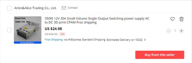
17. Power unit - 1 pcs. - $24.28.
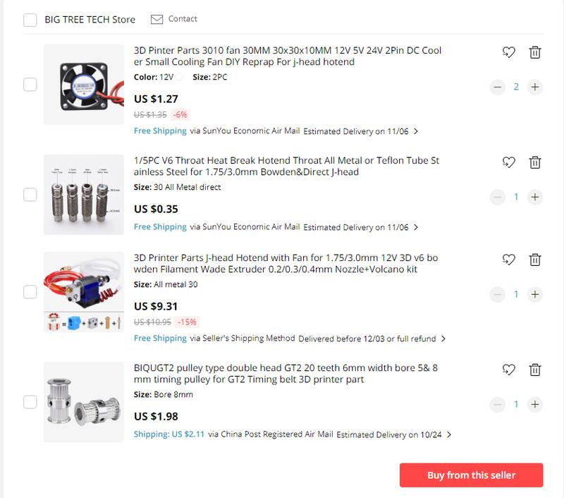
18. HotEnd e3d v6 - $9.31 for 1.75 or 3 mm and a heat break – 1 pcs. for $0.35 (not necessary).
19. Air conditioning unit for components - 2 pcs. - $2.54.
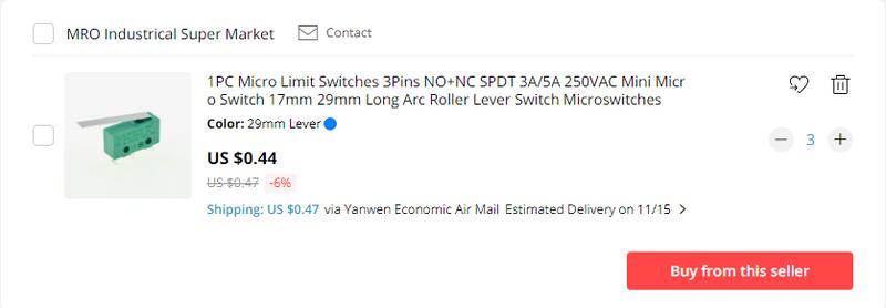
20. Limit switches with a long lever - 3 pcs. - $1.79
21. Driving pulleys with 20 teeth for 8 mm shafts - 8 pcs. - $10.10.
22. GT2 timing pulleys with 20 teeth for 5 mm shafts - 2 pcs. - $1.24.
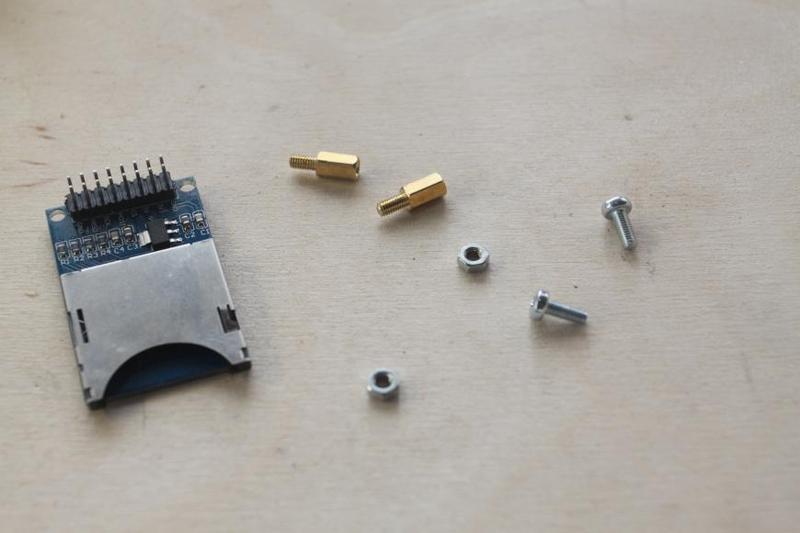
23. Card reader - 1 pcs. - $0.66.
24. Arduino Mega 2560 + RAMPS 1.4 + A4988 (4 pcs.) - 1 package - $17.02.
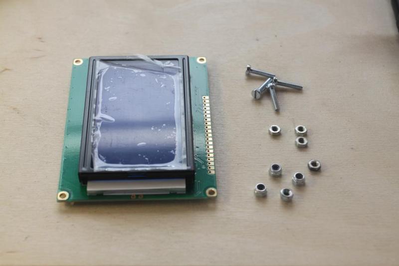
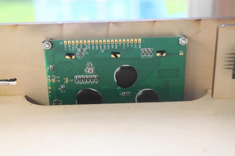
25. LCD display 12864 - 1 pcs - $4.69.
26. Clutch springs - 4 pcs. - Brake pad springs will do.
27. DuPont Housing: this and this
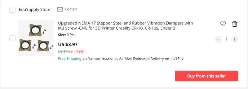
28. Dampers - 1-2 pcs. (not necessary) $4.16 for a package of 3 pcs.
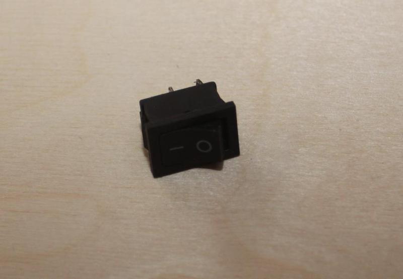
29. Backlight switch - 1 pcs. (not necessary) - $0.92 for 5 pcs.
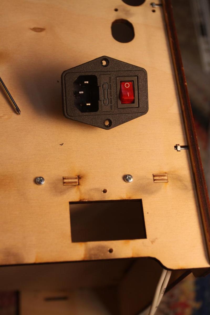
30. Plug socket with a fuse holder and a switch - $6.40 for 5 pcs. (not necessary).
31. Cable braiding - 3 m 8 mm - $4.99 (not necessary).
32. Heatsinks - 4 pcs. (not necessary) - 10 pcs. for $6.49.
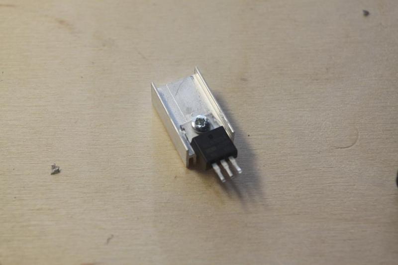
33. Transistor - 1 pcs. - $3.78 for 5 pcs. and transistor radiator - 1 pcs. - $1.05 for 10 pcs. (not necessary).
Instead of substituting the transistor with a RAMPS, a car relay or a solid state relay can be used. If the latter is used, there may be problems: it might just melt down)
34. Clamps - 4 pcs. - $1.49 (can be substituted with office clamps).
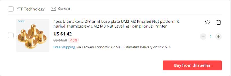
35. Knobs for bed leveling - 3 pcs. - $1.45 (can be substituted with М3 knobs).
36. Air conditioning unit for a circuit board – 1 pcs. - $8.39 (can be substituted with one designed for a power unit).
37. LED strip - 1 meter - $3.36 for 5 meters (not necessary).
38. Flexible multi-line wires, at least 0.22 mm in diameter, approximately 15 m. In this particular case, so-called intercom wires were used.
39. 2.5 mm flexible multi-line wires, approximately 2 m.
40. Reinforcement heating for these wires.
41. If you face difficulties finding mounting components and wires in proximity, go to the sam place where the rest of the components were bought – everything can be found here:
41.1. Screw M2.5x20 6 pcs.
41.2. Screw M3x10 30 pcs.
41.3. Screw M3x12 30 pcs.
41.4. Screw M3x14 15 pcs.
41.5. Screw M3x16 85 pcs.
41.6. Screw M3x20 20 pcs.
41.7. Screw M3x25 20 pcs.
41.8. Screw M3x30 21 pcs.
41.9. Screw M3x4 2 pcs.
41.10. Screw M3X5 10 pcs.
41.11. Screw M3X6 10 pcs.
41.12. Screw M3X45 2 pcs.
41.13. Screw M3x8 10 pcs.
41.14. Nut M2.5 6 pcs.
41.15. Nut M3 130 pcs.
41.16. Self-locking counter nut M3 35 pcs.
41.17. Washer M2.5 6 pcs.
41.18. Cage washer or large washer M3 17 pcs.
42. Thermal adhesive – 1 pcs.– $0.81 (not necessary; nowadays, radiators tend to be self-adhesive, otherwise thermal paste can be applied)
43. Bed thermistor – 1 pcs. $0.76, buying some extra pcs. is advised: these things tear, break and malfunction.
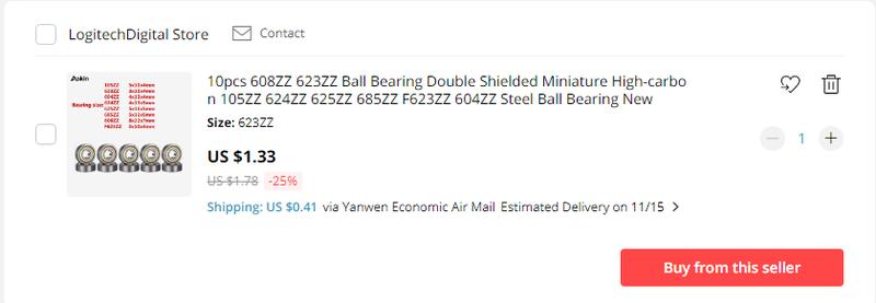
44. Bearing 623ZZ – 1 pcs. - $1.33 for 10 pcs.
45. Spool holder. It can also be printed.
46. Plastic components (we recommend printing everything with ABS, with 100% filling). If you don’t have the means to print those, then you can order them.
46.1. Washer 8,5*10,5*5 – 2 pcs.
46.2. Washer 8,5*10,5*10 – 5 pcs.
46.3. Washer 8,5*10,5*25 – 1 pcs.
46.4. Extruder part 1 – 1 pcs.
46.5. Extruder part 2 – 1 pcs.
46.6. Extruder part 3 – 1 pcs. or this one - 1 pcs.
46.7. Mounting unit E3D 1 part – 1 pcs.
46.8. Mounting unit E3D 2 part – 1 pcs.
46.9. Air cooling unit – 1 pcs.
47. Tools:
47.1. Screwdrivers for required screws.
47.2. Pliers.
47.3. Soldering iron and solder.
47.4. Multimeter.
47.5. Sandpaper.
47.6. Oil (silicon oil is recommended).
47.7. Cable ties.
47.8. Precision knife or box cutter.
47.9. Duct tape.
47.10. Having a crimping unit for Dupont plugs is desirable, but in any event pliers will do. We can also recommend using clamping units for isolated pin bush tips; the latter need to be compatible with the size of the wires.
47.11. Glue stick, we recommend the brands UHU and 3M Skotch.
So, here’s the completed AliExpress order:


We’ll be glad if any user joins us and crafts their own printer as well.
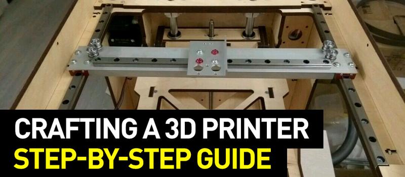
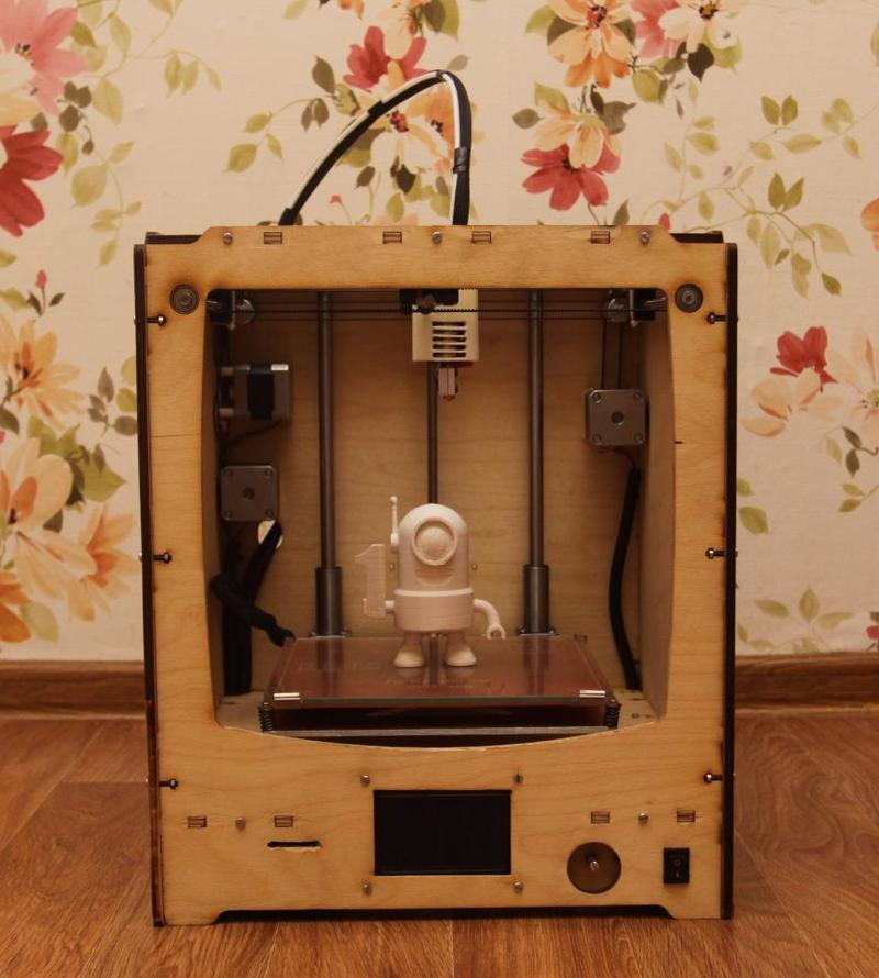
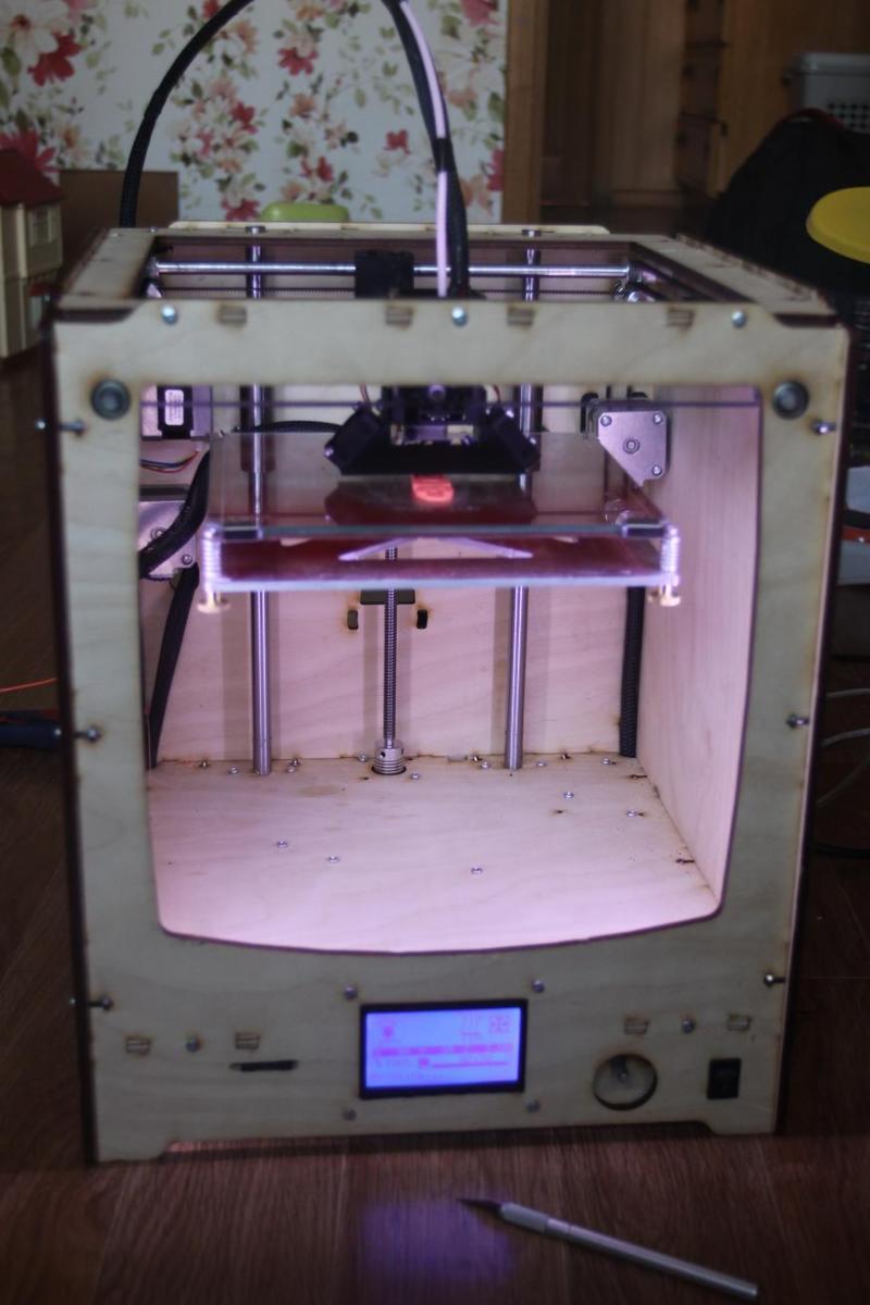
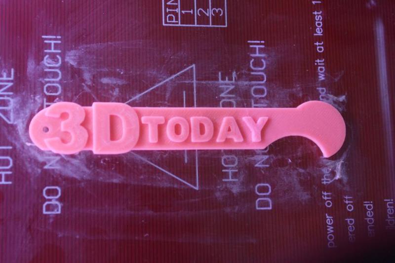
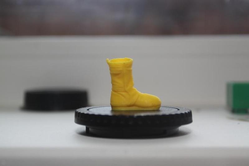
Eventually, we will get a functioning machine like this.
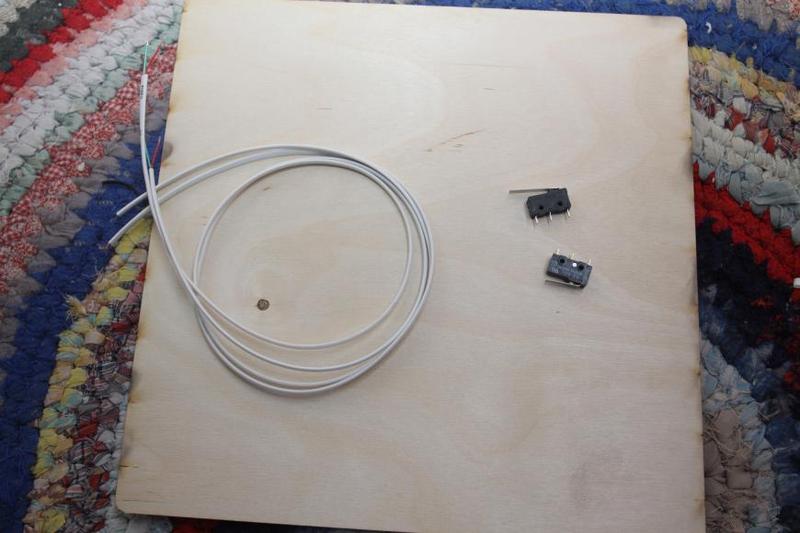
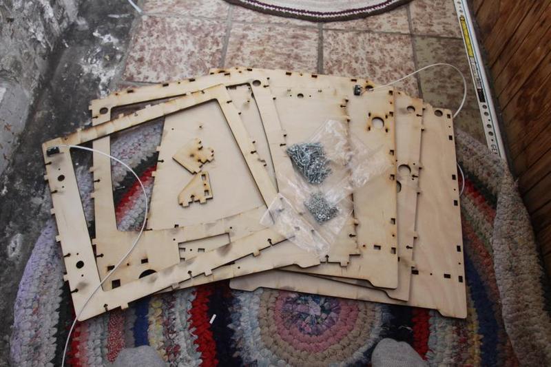
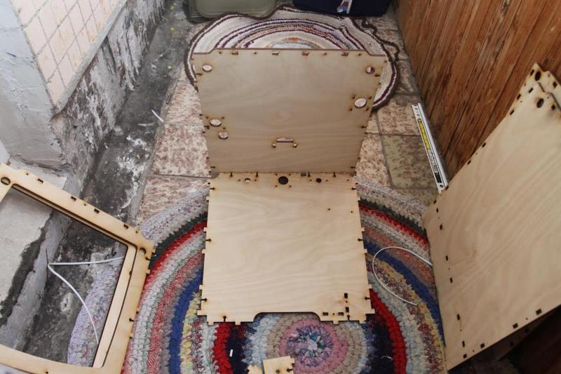
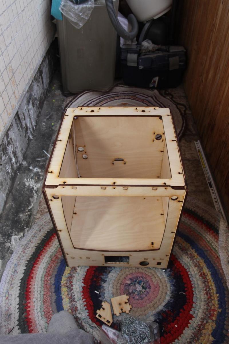
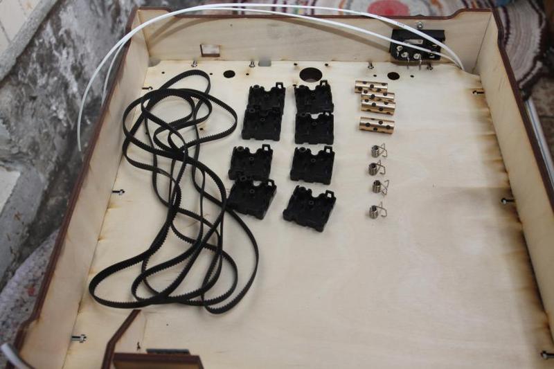
So, we've bought all the components required for the assembly of our printer, and what we now have looks like this:
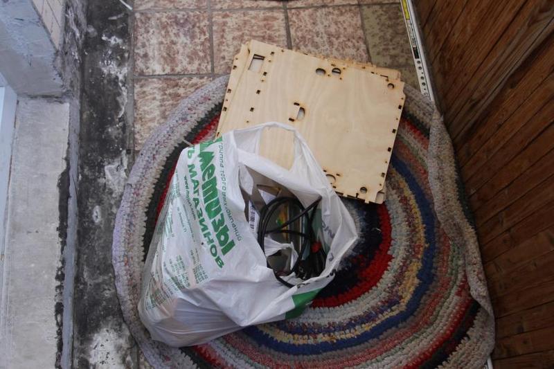
Since this 3D printer was assembled at home by an enthusiast, we can’t show you all of the parts laying on the floor. It’s worth noting that losing components in your apartment is very easy, so pay attention.
You'll need:
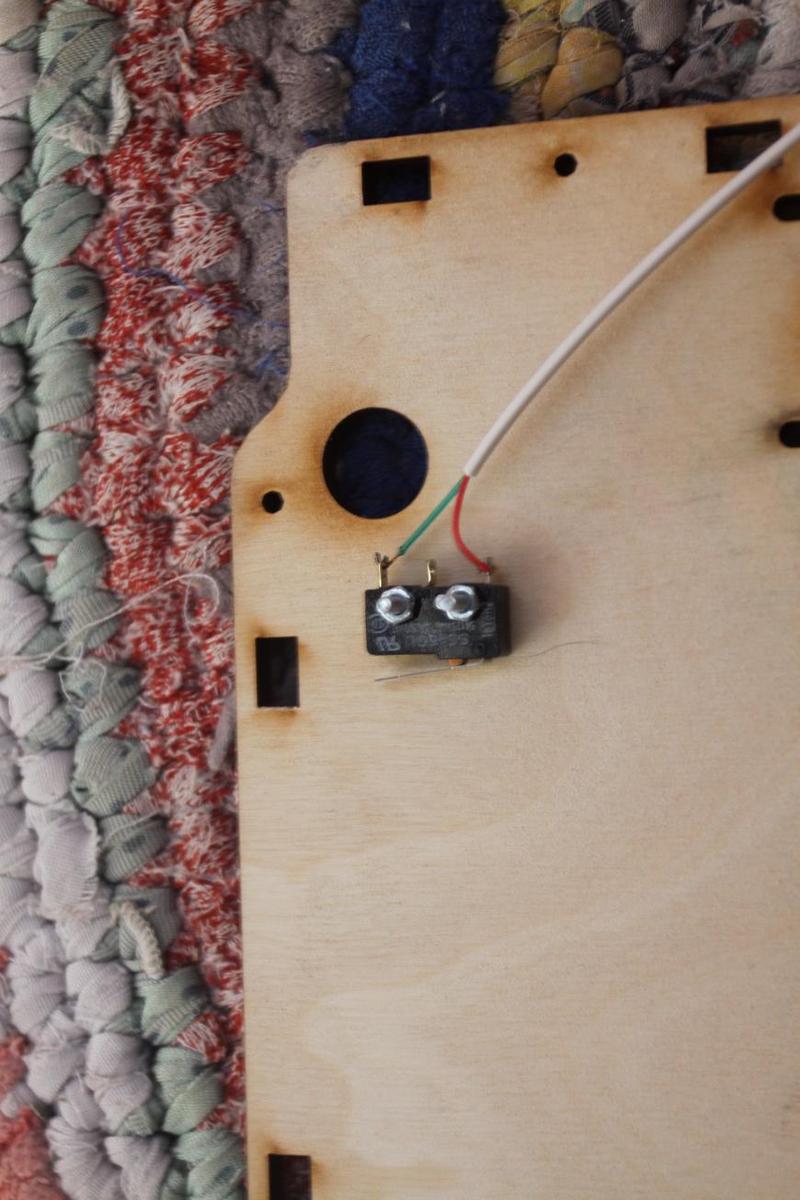
Solder the wires to the microswitches. We recommend using C (closed) and NC (normally closed) contacts for microswitches! “Normally closed” means that the circuit is closed when at rest and opened when pressed.
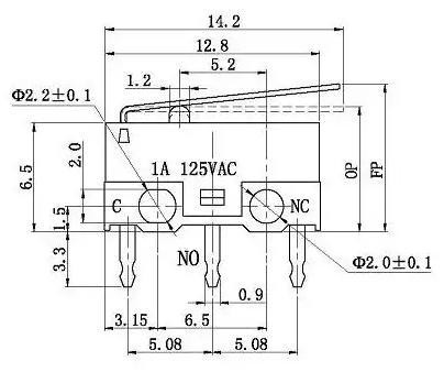
In certain cases, contacts are marked with numbers — 1 and 2.
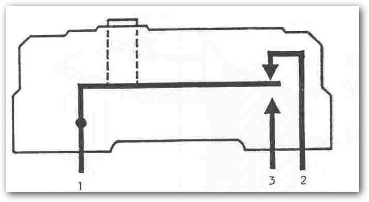
What we need this for is additional verification of the printer's reliability: if something's wrong with the switches, the print head won't be able to take the HOME position.
You'll need:
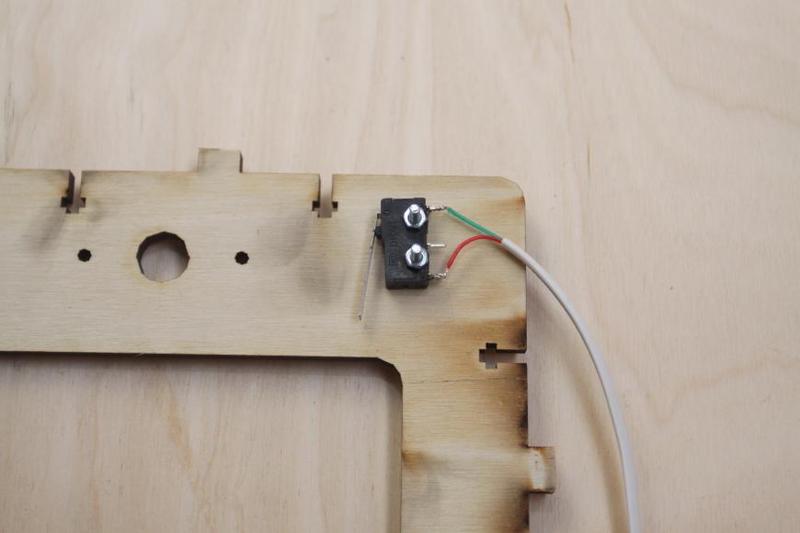
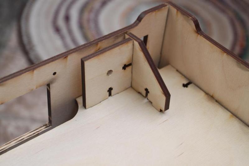
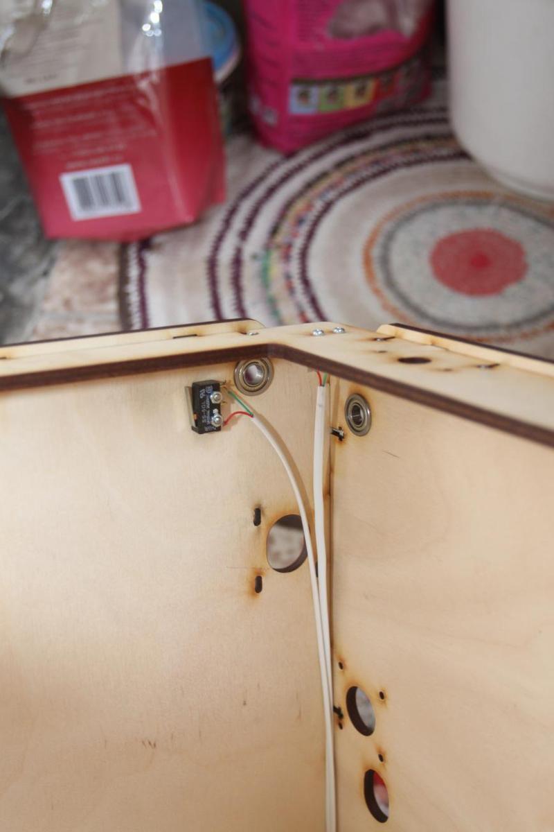
NOTE! If you use microswitches with levers of different lengths, the long-levered microswitch is to be installed for the X-axis, and a standard lever will do for the Y-axis.
NOTE! Don’t tighten the microswitches excessively: they are very fragile, and manual tightening is good enough.
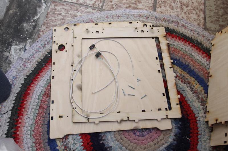
Install the microswitches, as shown in the pictures.
X-axis:
Y-axis:
You'll need:
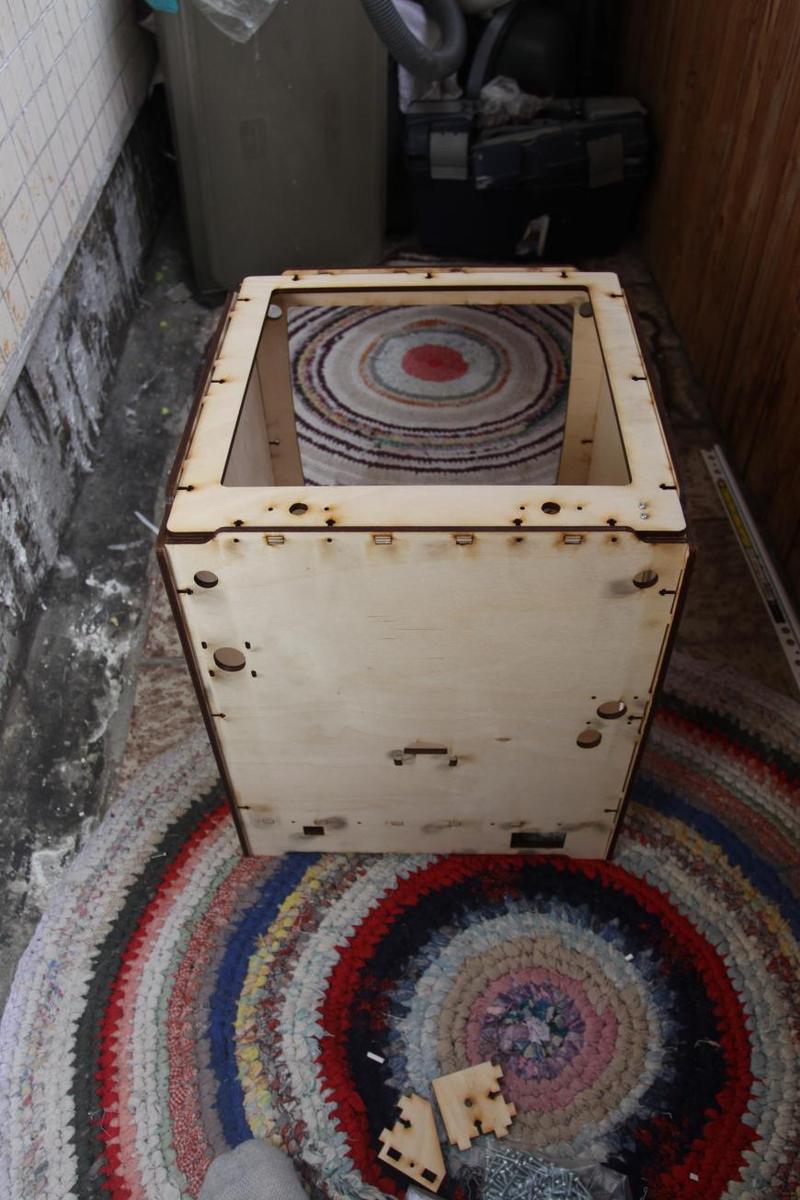
Order of the assembly:
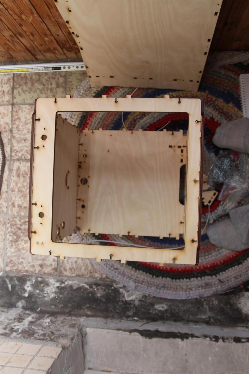
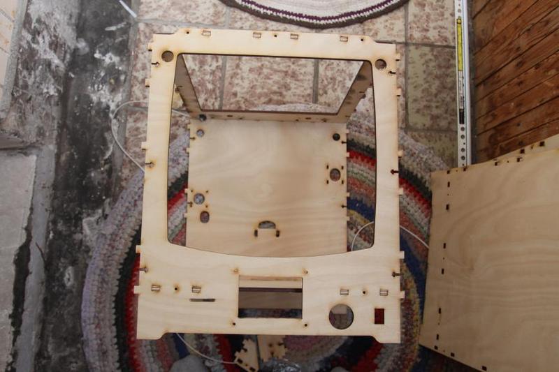
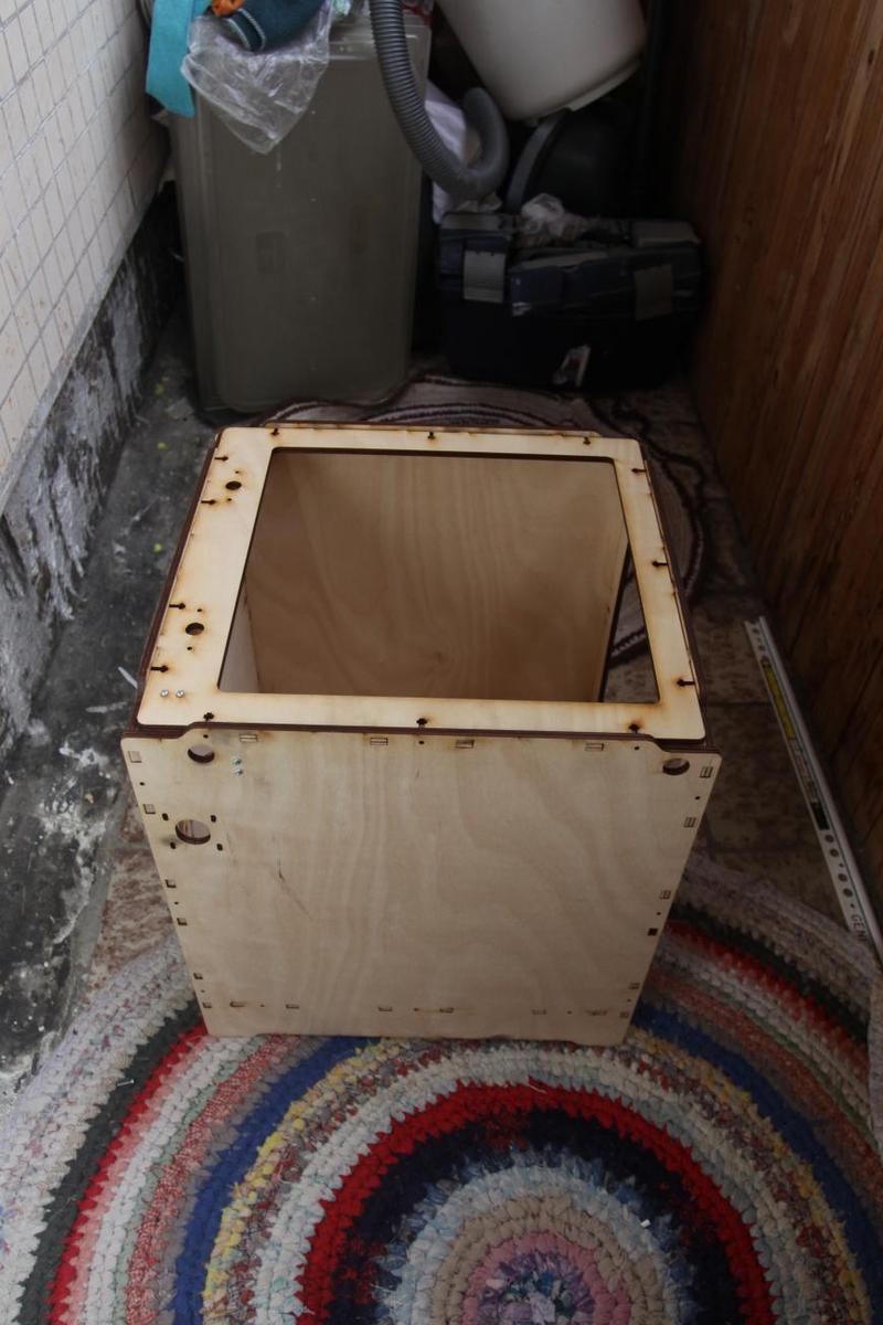
Finished frame:
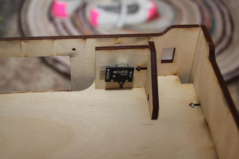
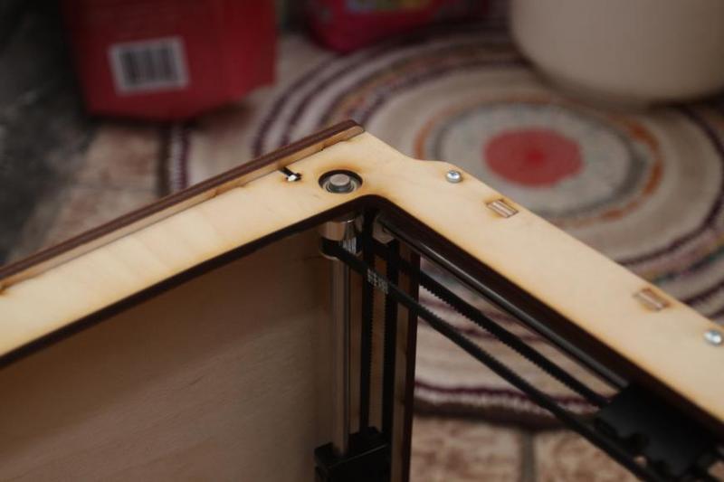
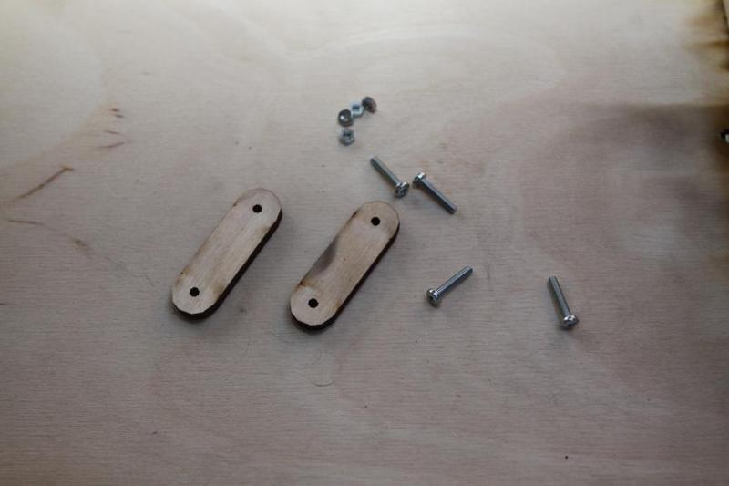
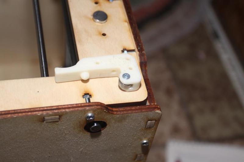
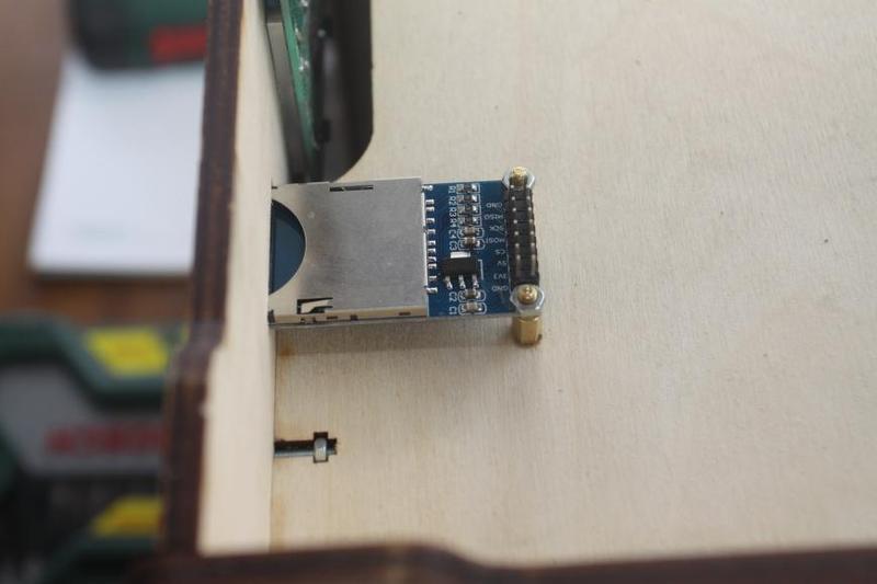
Fix the encoder.
!!!NOTE!!! The screwing needs to be done very carefully, and it’s better to drill a hole if the process is difficult, since the encoder board might be torn very easily.
You'll need:
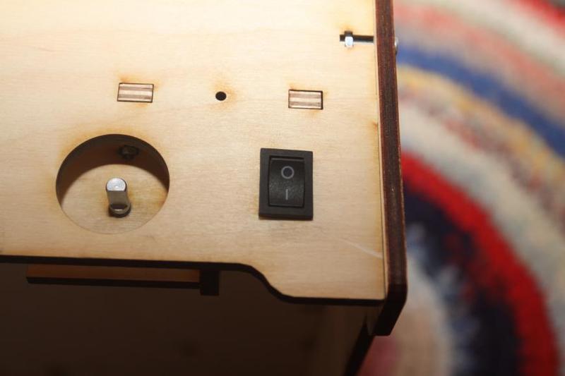
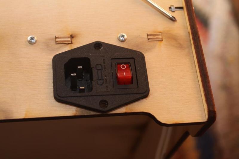
Insert the switch all the way into the frame.
You'll need:
You'll need:
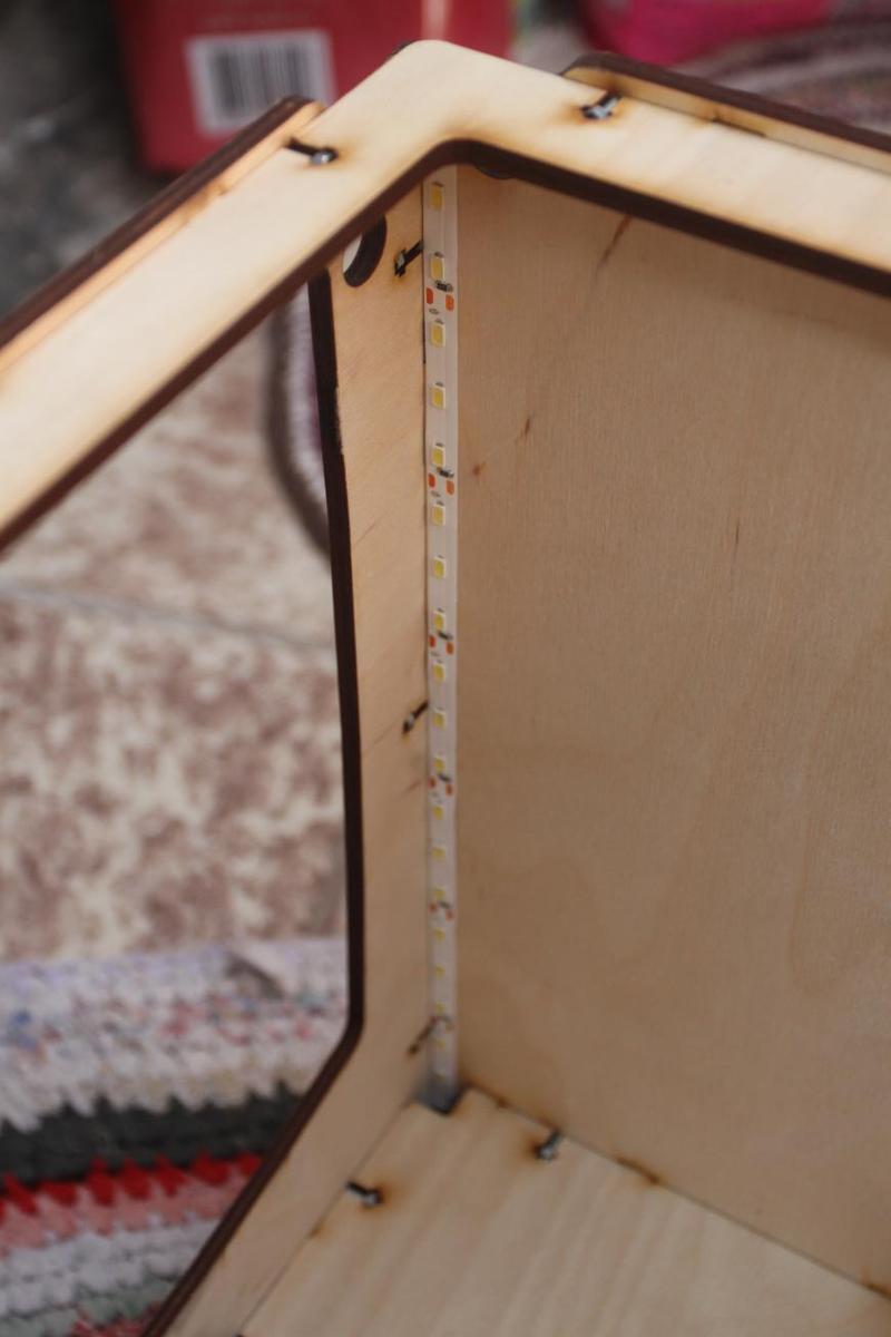
Stick the LED strip inside the printer along the front edge on the right, left and upper panels.
You'll need:
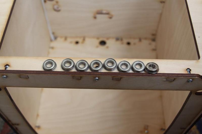
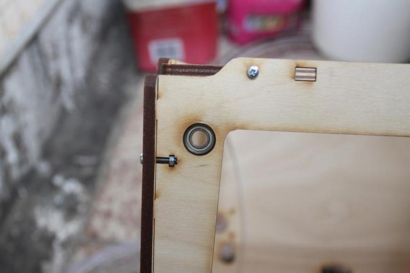
Insert the bearings into the holes with the flange facing the inside part of the frame; the installation requires slight effort.
You'll need:
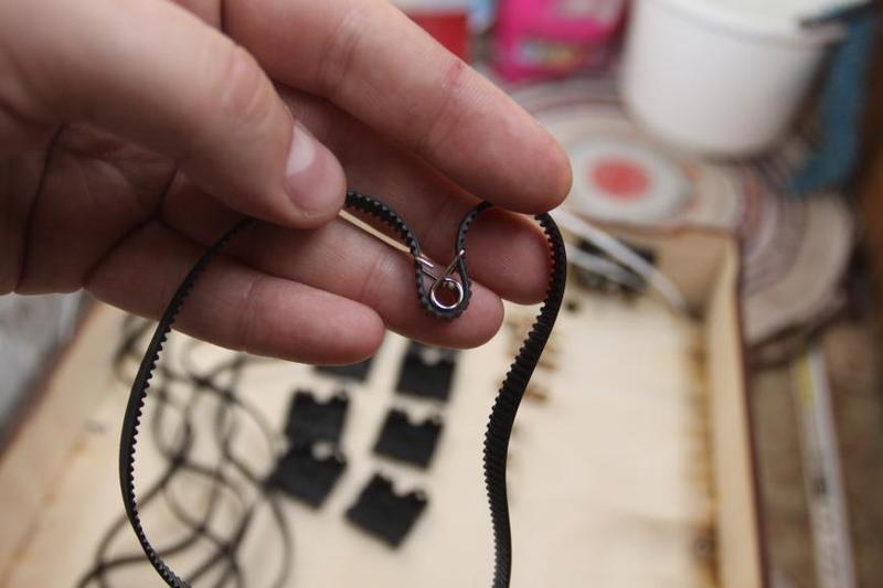
To assemble the carriages, you need to show some incredible dexterity.
The belt is stretched as shown in the picture, with the smooth side facing the spring.
Insert the copper sleeve into the frame.
Install the spring with a belt into the frame, as shown in the picture.
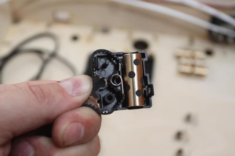
Then close it with the second detail of the frame until it clicks four times and ensure that the belt isn’t trapped and is capable of amortization.
You'll need:
The algorithm of the installation is as follows:
First, install the outermost shaft; to be placed on it, between the bearings, are, from left to right:
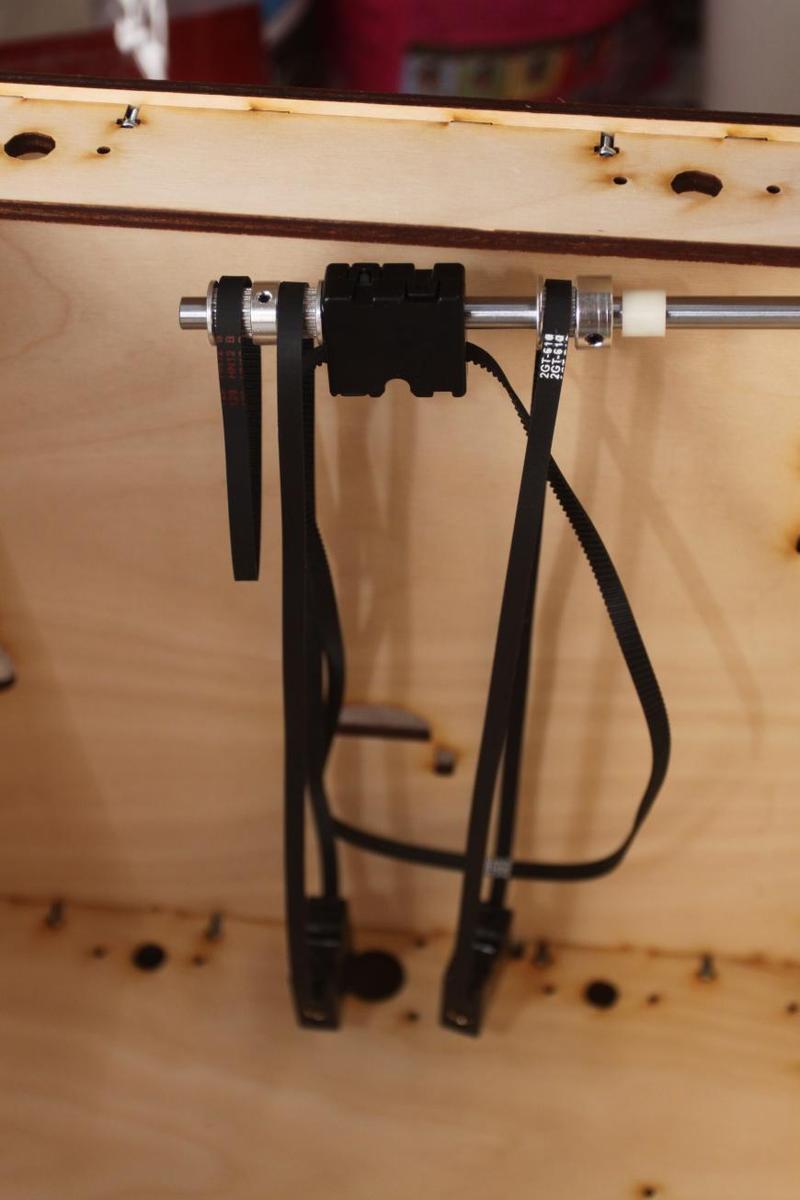
Second, install the front axis, and to be placed on it are, from left to right:
Extend the pulleys to the sides with nuts, to the very bearings. Then level the carriages relative to each other and tighten the screws on the pulleys.
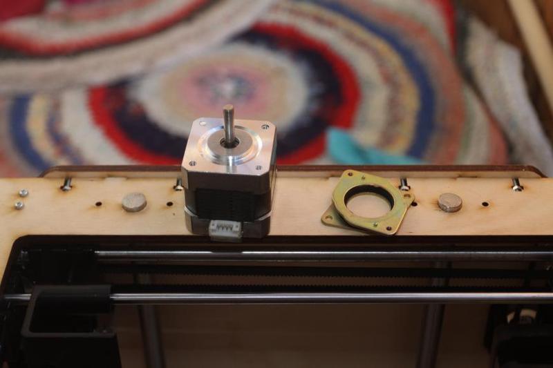
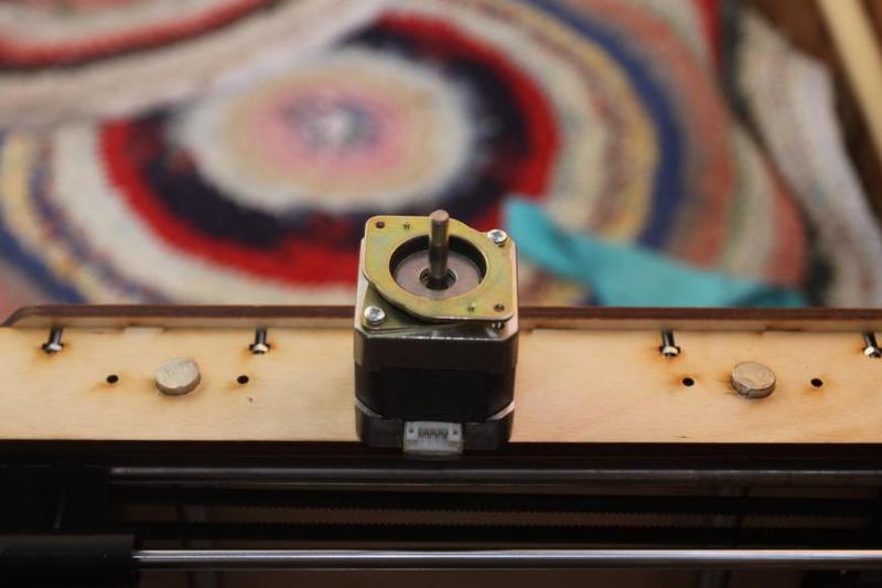
You'll need:
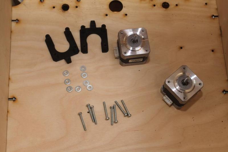
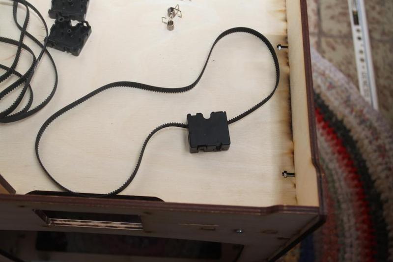
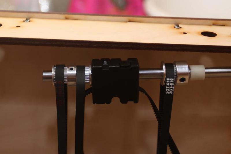
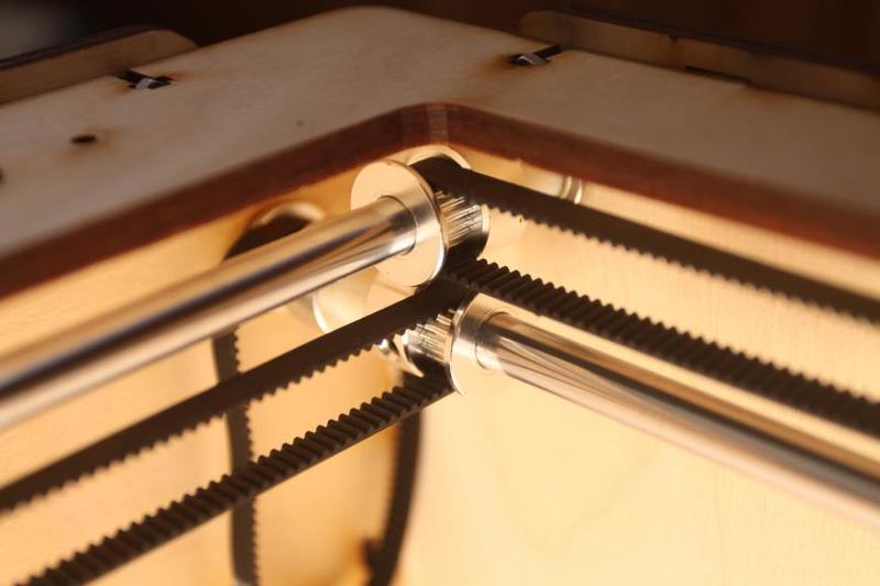
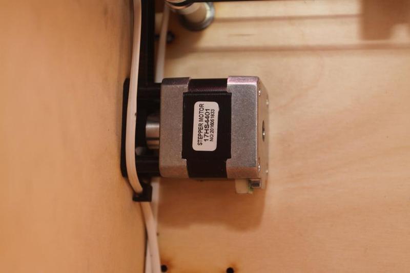
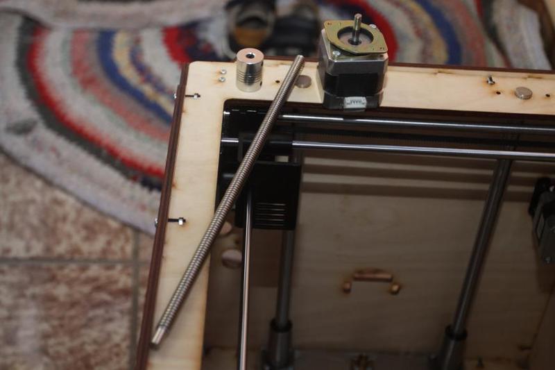
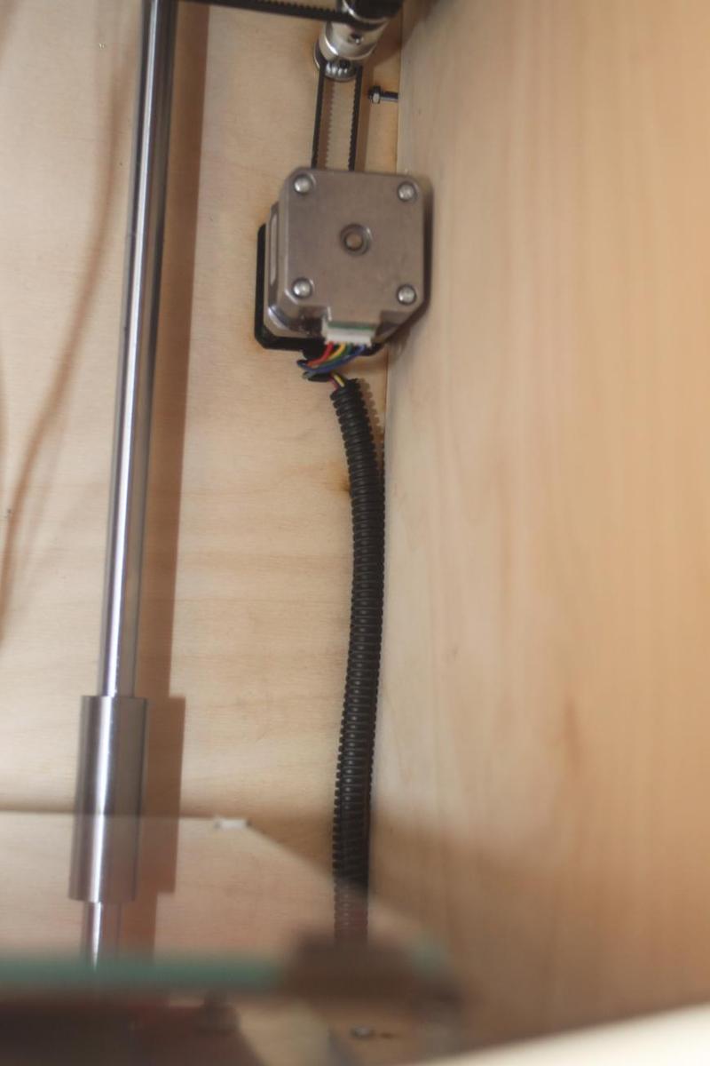
The pulleys are mounted with screws very close to the stepper motor.
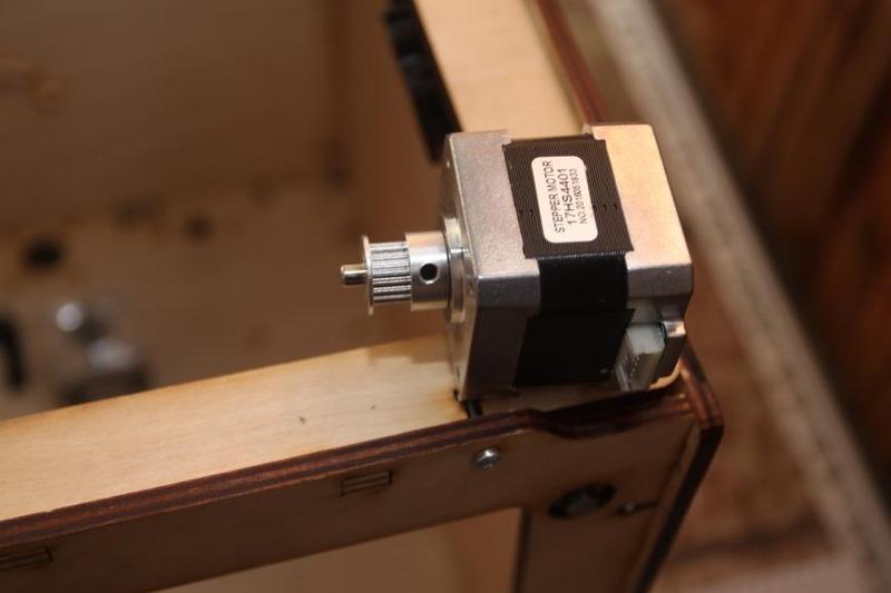
Screw the stepper motors with the use of spacers and bracer; a small belt is put onto the pulley and tightened.
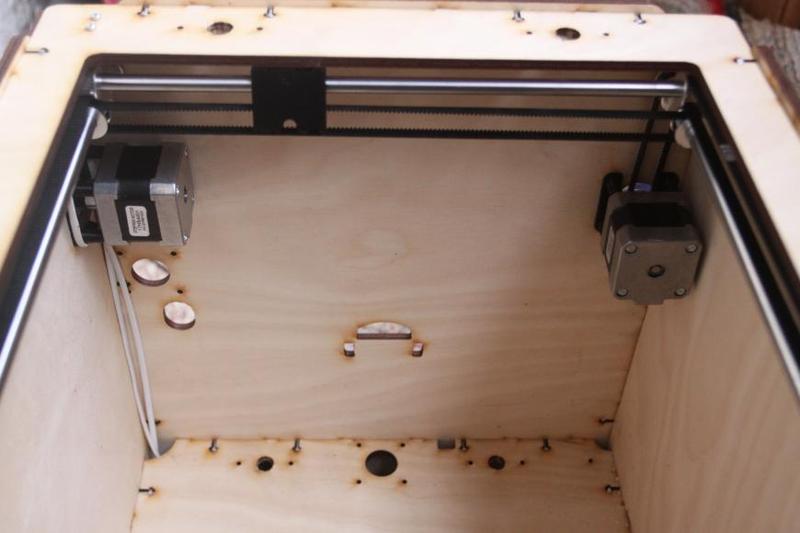
You'll need:
Insert the bearings into the holes.
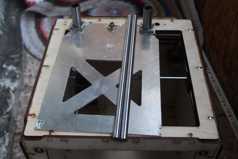
You'll need:
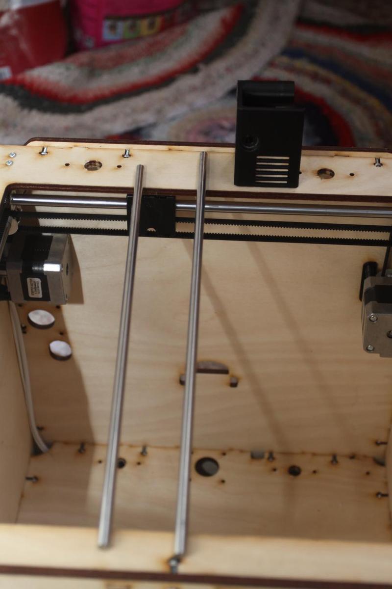
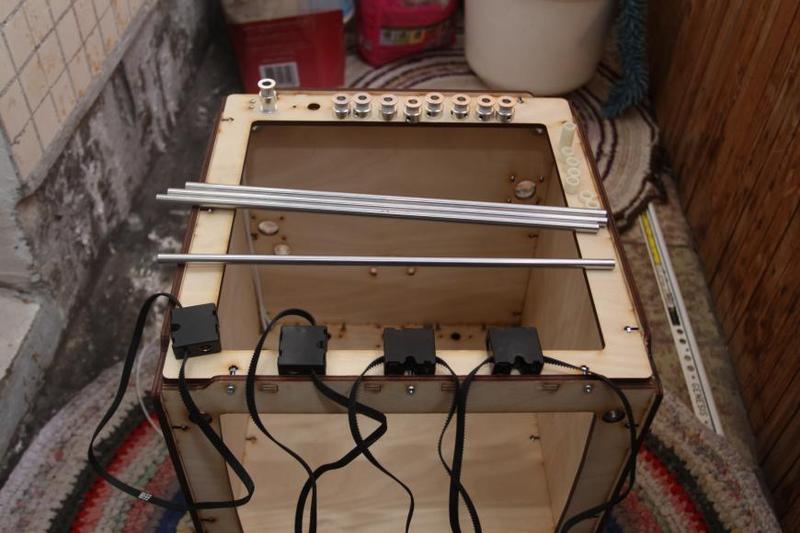
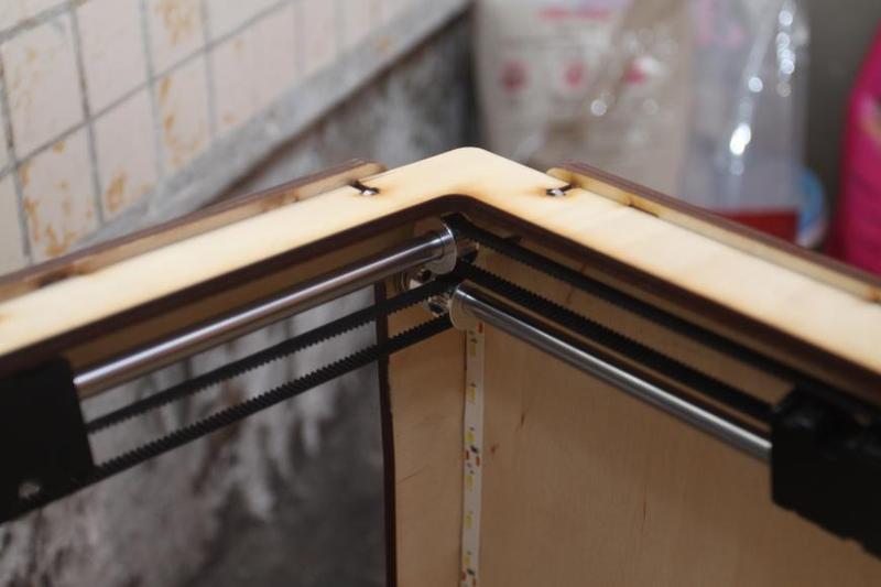
Install the shafts into the bearings, with the short one (300.5 mm) placed lengthwise and the long one (320 mm) across.
Insert them into the sleeves until it clicks. Sometimes carriages don’t hold the shafts strongly enough — a drop of adhesive can fix the problem.
At the rear, the shafts mustn’t protrude from the carriage — otherwise, collisions with the shafts of the Z-axis will happen.
You'll need:
Assemble it all as shown in the picture without tightening the bearings — the tightening needs to be done after installing the components into the frame.
You'll need:
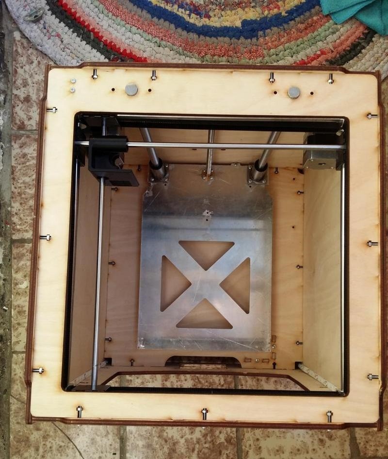
Insert the cover plugs into the lower part of the frame.
Put the shafts into the holes at the top of the frame, mount them to the bed and put them into the sleeves until it click.
You'll need:
Install the damper and fasten it with screws:
You’ll need:
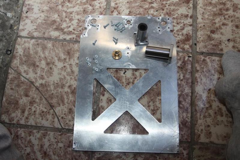
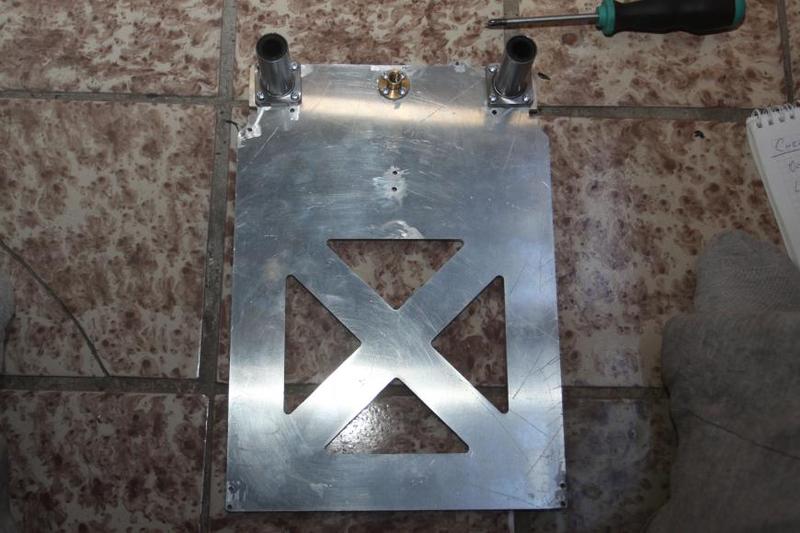
Screw all the 3 components together, as it is shown in the picture.
You’ll need:
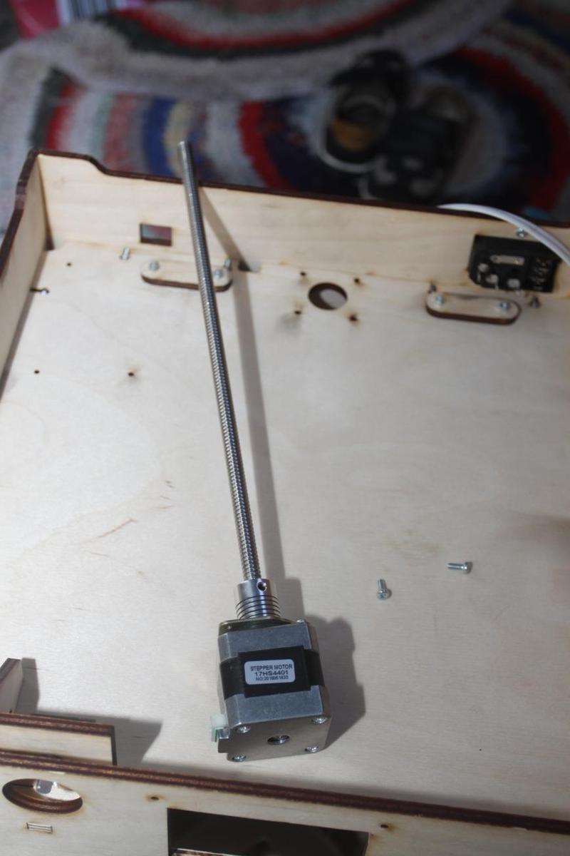
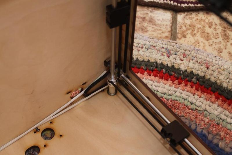
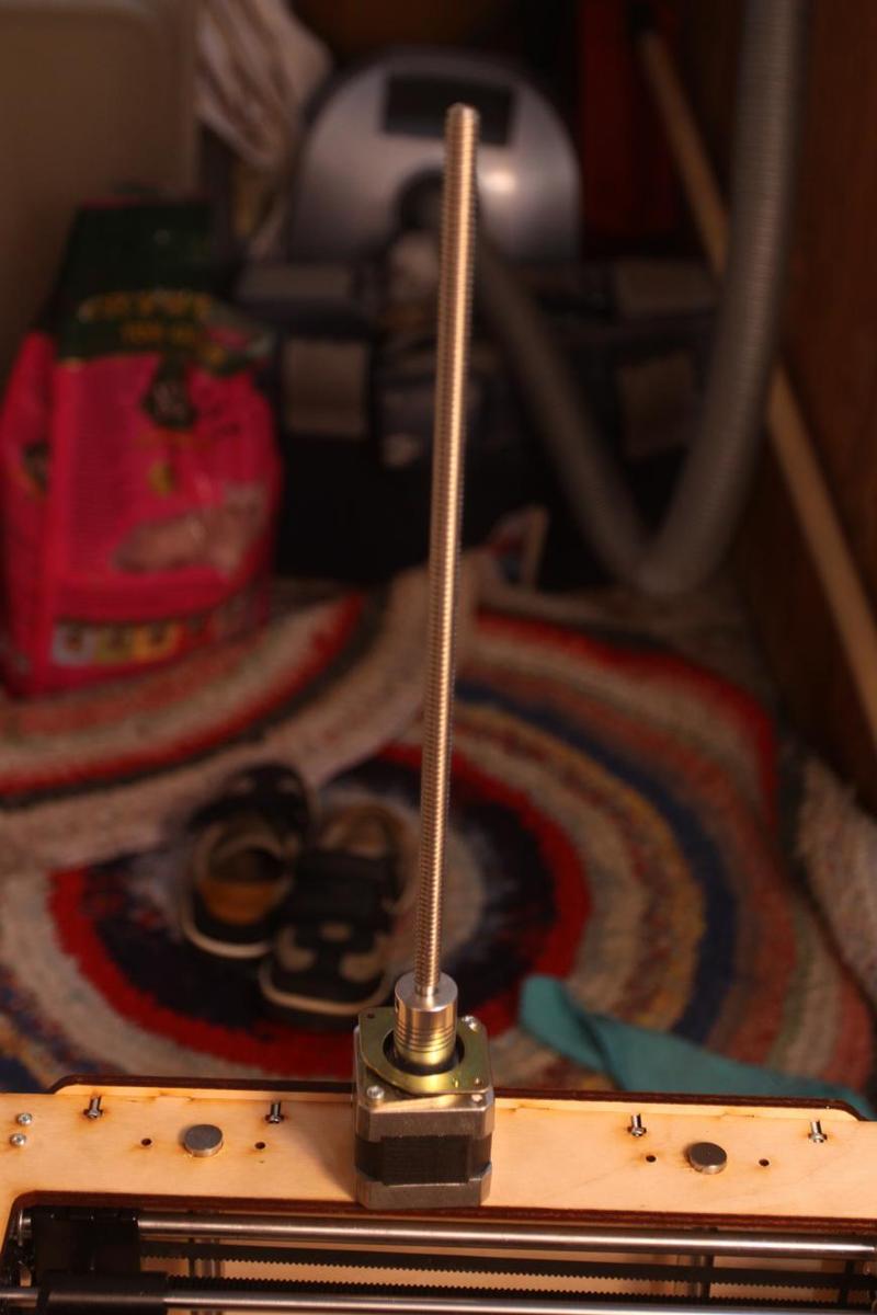
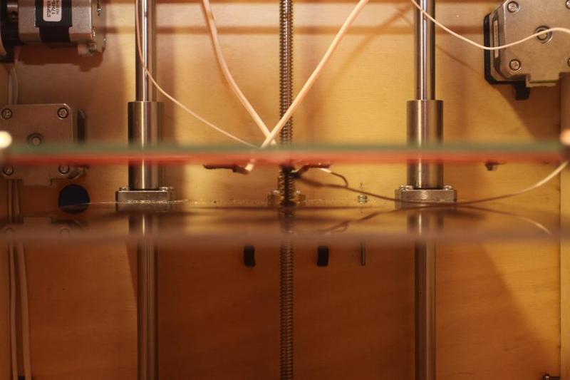
Insert the trapezoidal screw into the nut installed onto the bed and attach the stepper motor to the frame with screws:
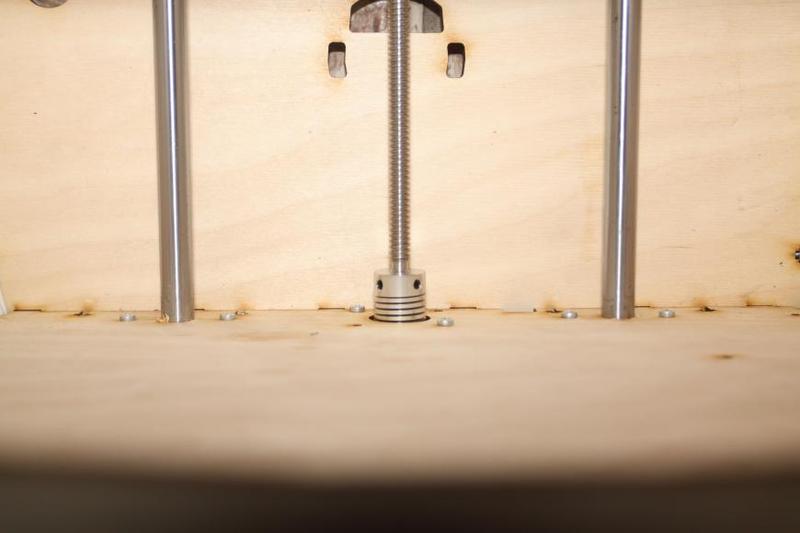
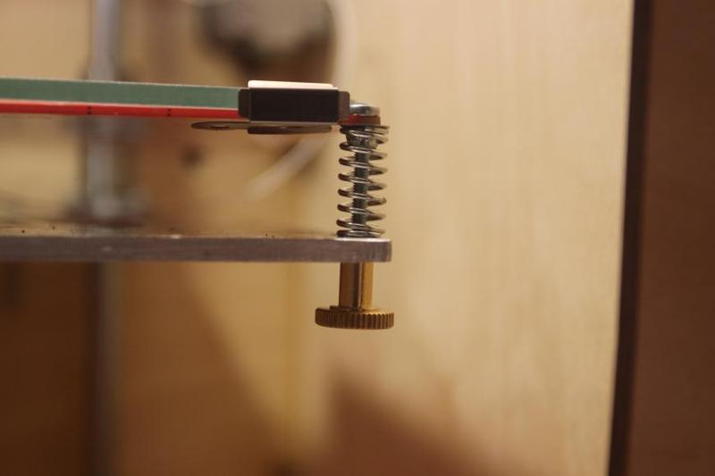
You’ll need:
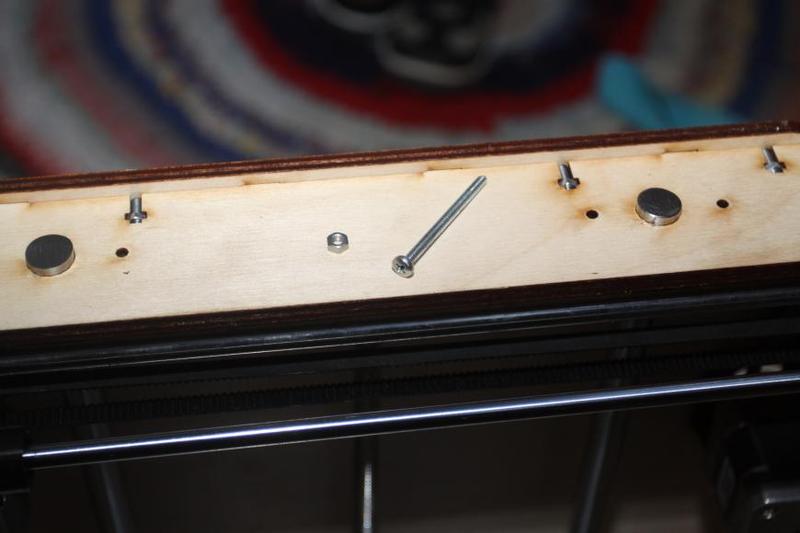
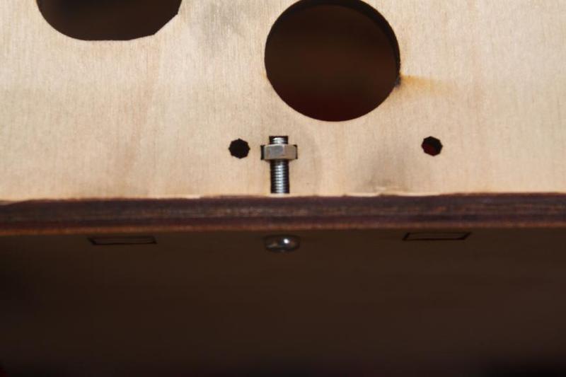
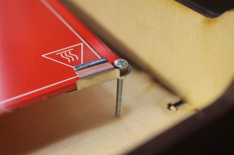
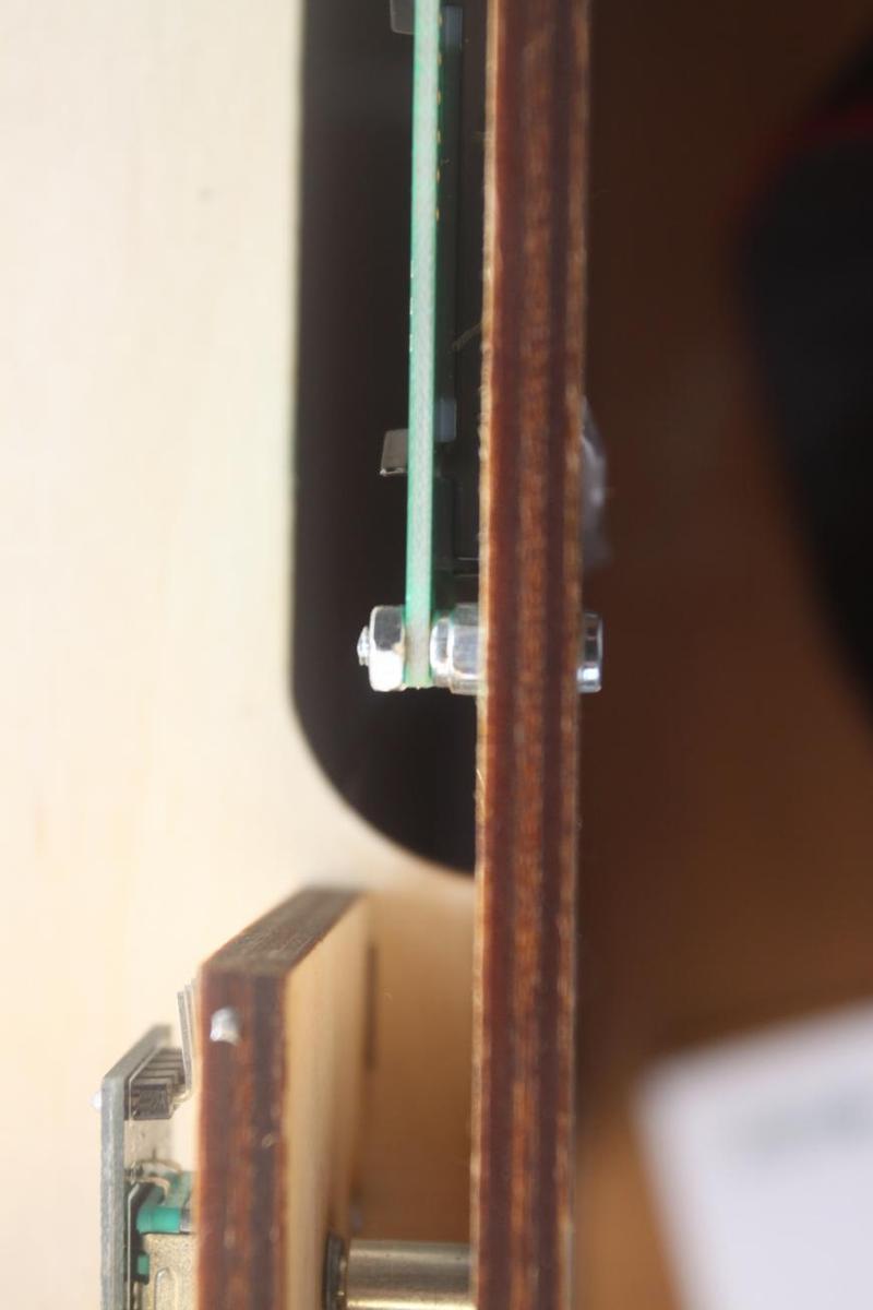
Put the screw into the hole in the bed and fasten it with a nut.
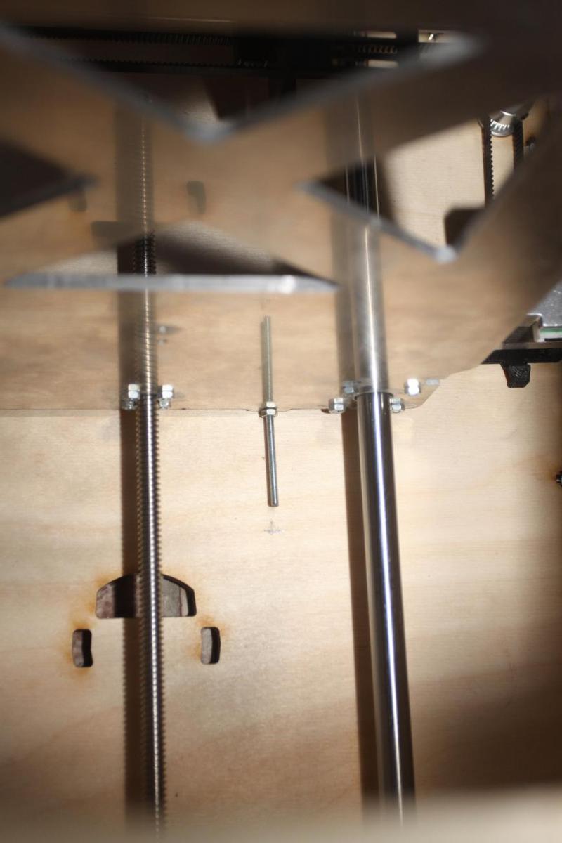
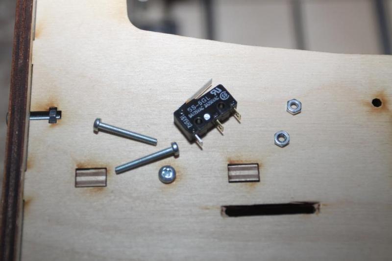
Place the bed in the lowest position and mark location-wise the position of the microswitch, in which it will be pressed by this screw,
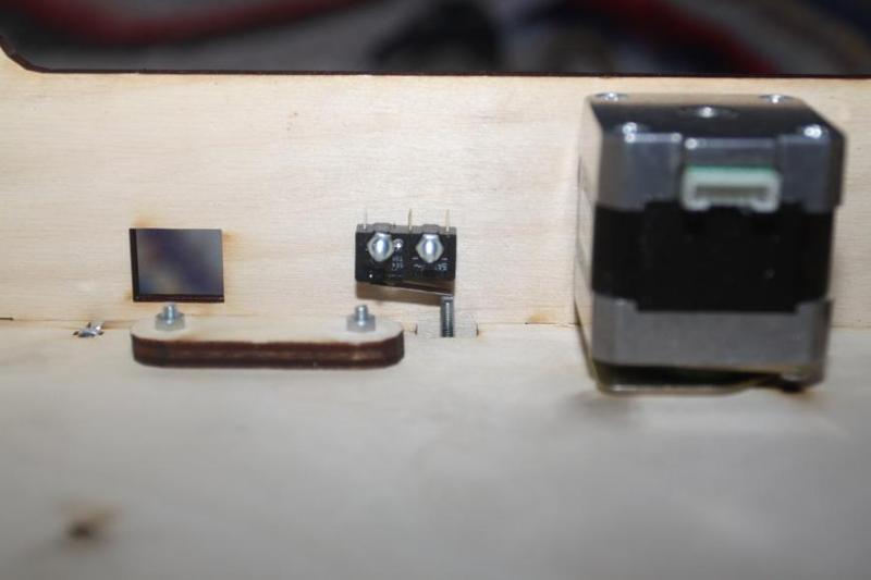
Drill holes and fasten the microswitch with screws and nuts.
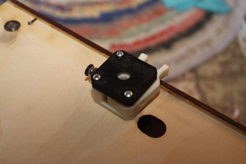
You’ll need:
Install them like it is shown in the picture:
Some further adjustments might be required afterward.
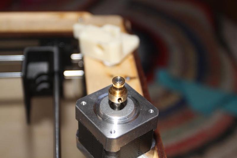
Strong fastening is obligatory: this gear wheel has only one mounting screw, and if it loosens, it might be difficult to locate the reason why the filament isn't fed.
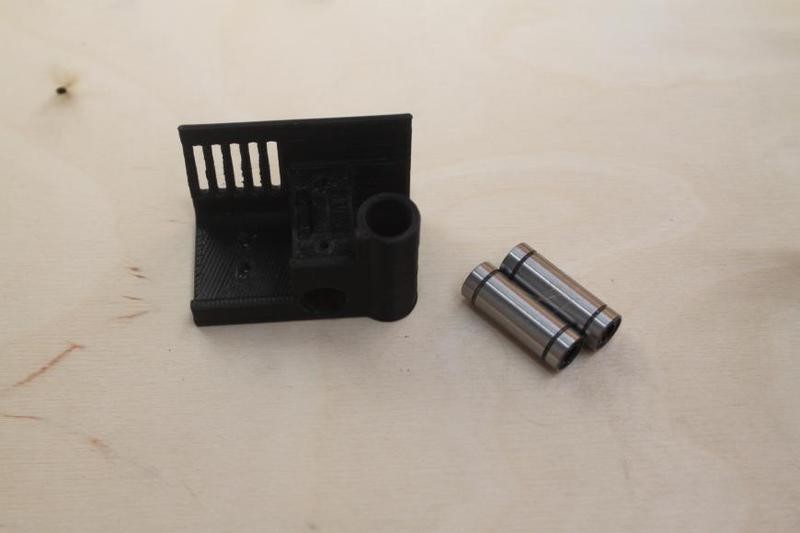
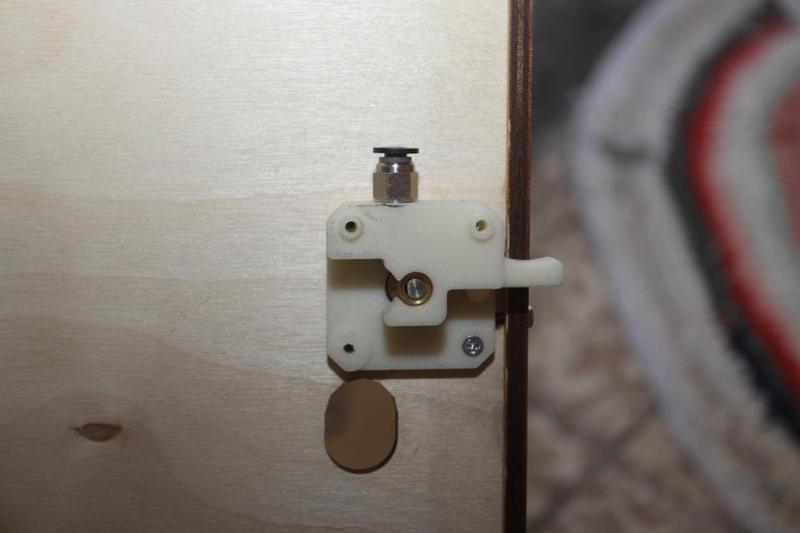
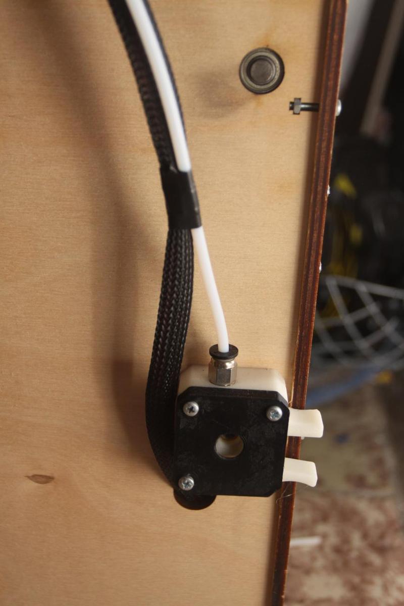
You'll need:
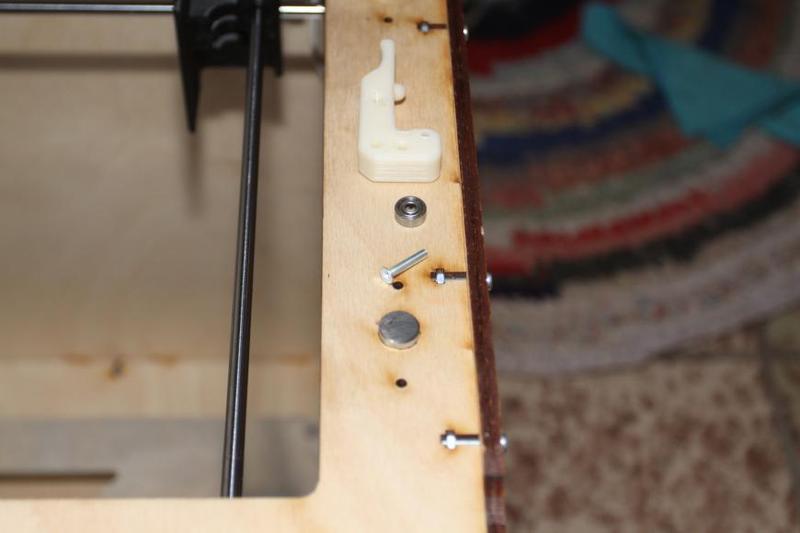
After assembling the clip, you’ll get something like this:
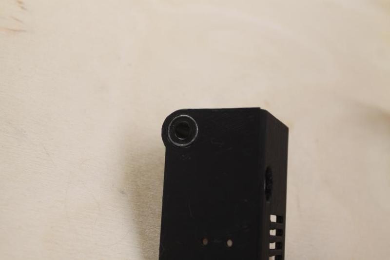
You'll need:
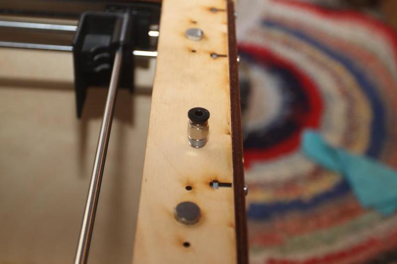
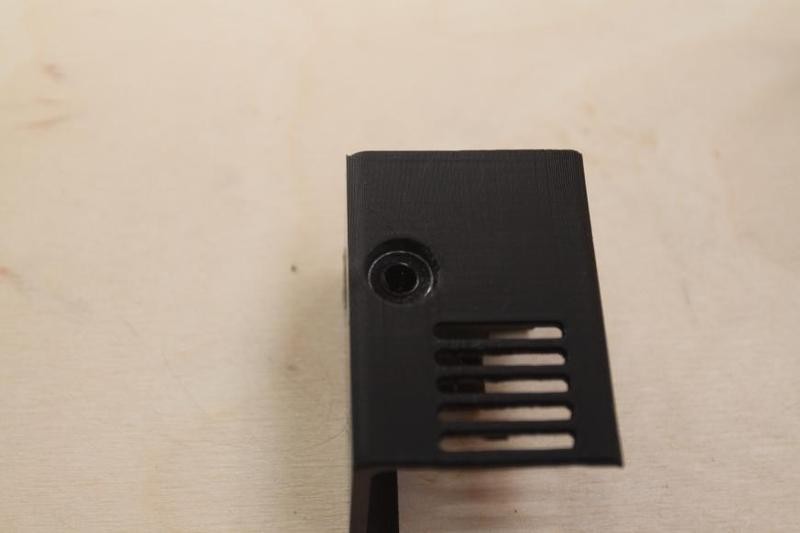
Just screw it into the extruder, and it should look like this:
And the last step:
You'll need:
The assembly of the printer took the enthusiast 4 evenings. Each session lasted about one hour, with many photographs and notes taken in order to not miss anything. That means that for those assembling their printer for the first time, it's probably going to take, roughly, the same amount of time — and those who already have a background will perhaps need twice as little time. It's really quite easy.
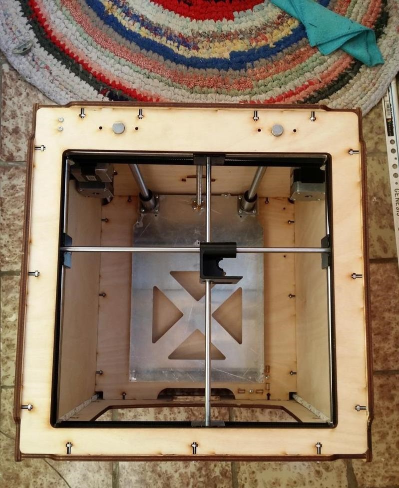
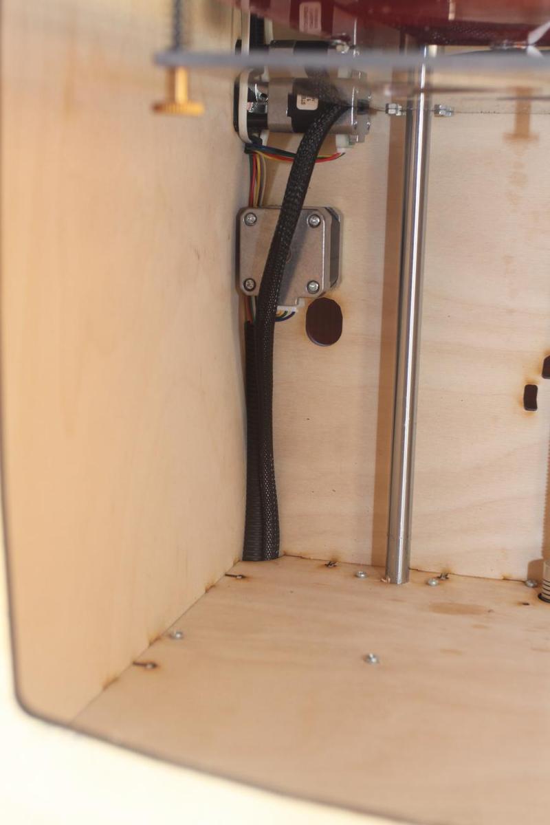
Now we can safely say that the mechanical side of the printer is done: we can move the bed up and down, move the print head carriage forward, backward, to the right and to the left.
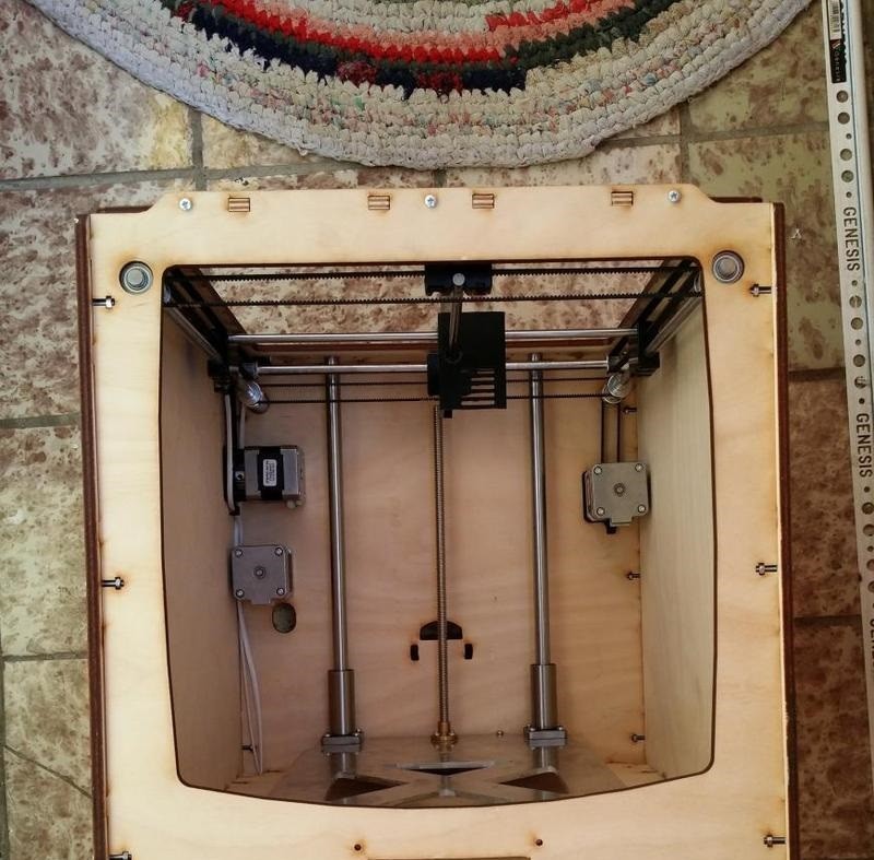
At this point, you have practically finished our printer from a mechanical point of view.
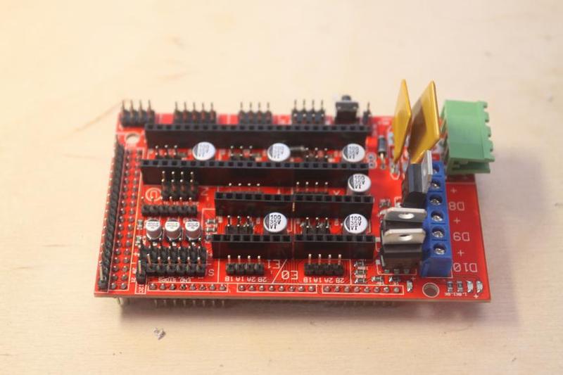
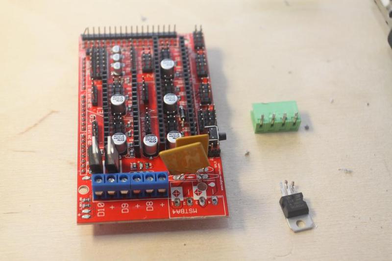
We now proceed to fill our printer with electronic components:
Customizing RAMPS is necessary for the bed to get heated quickly; it’s also necessary if we want to avoid using a relay and to do away with the power socket, soldering everything directly to the board instead. This step isn’t necessary.
You'll need:
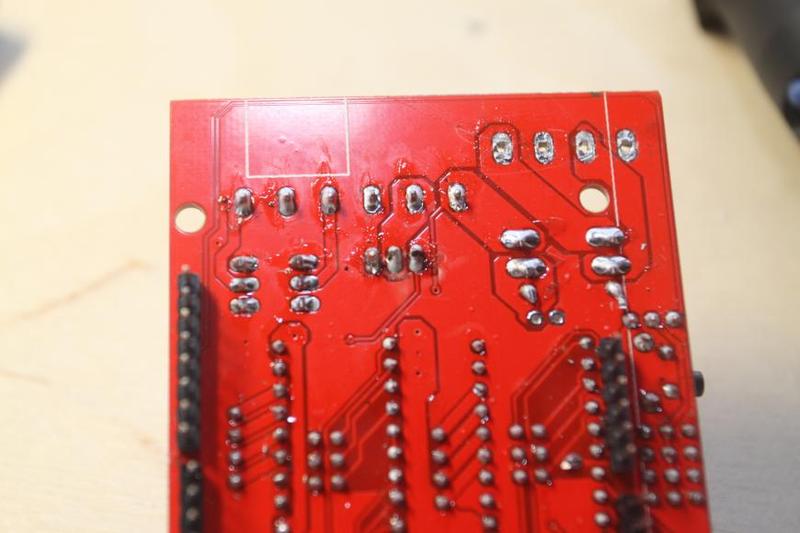
Unsolder the transistor:
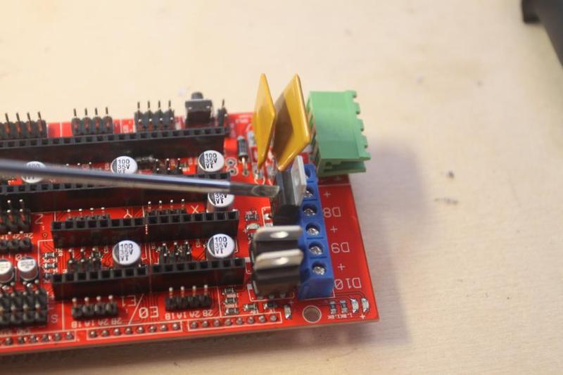
Unsolder the socket:
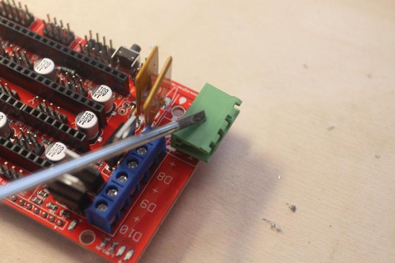
The result:
Install the jumper pins:
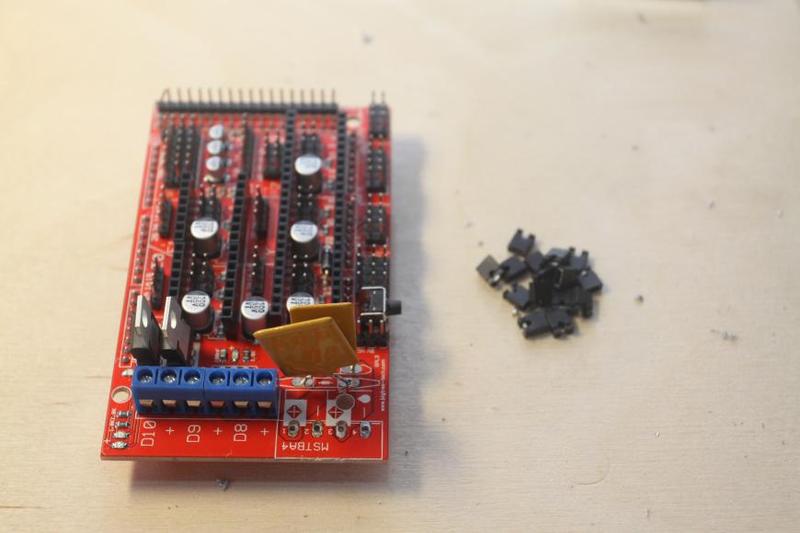
Like this:
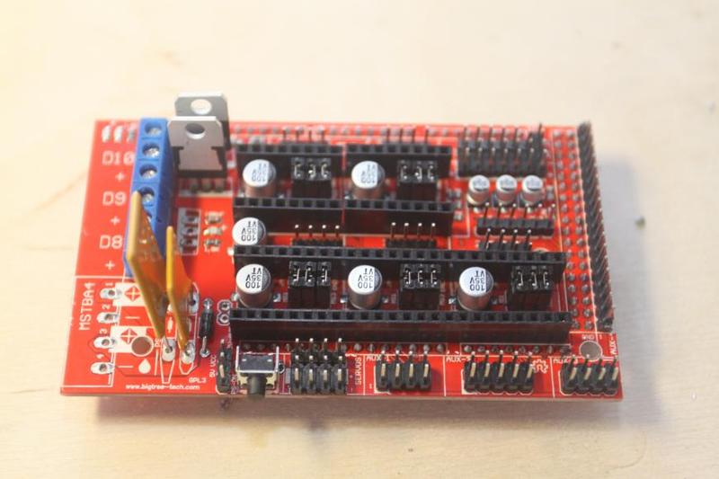
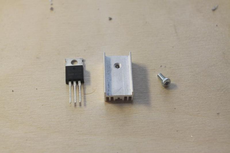
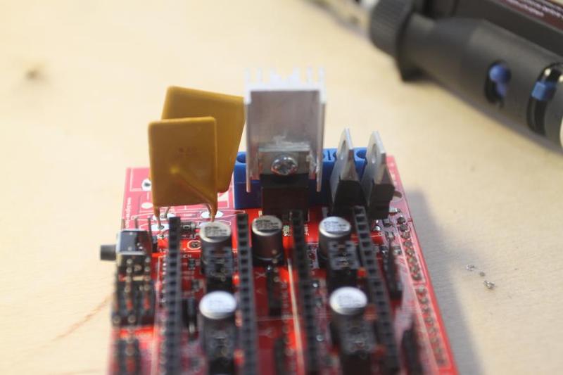
Screw the radiator to the transistors, first applying some thermal paste to the junction:
The result:
Solder the new transistor to where the old one was:
You'll need:
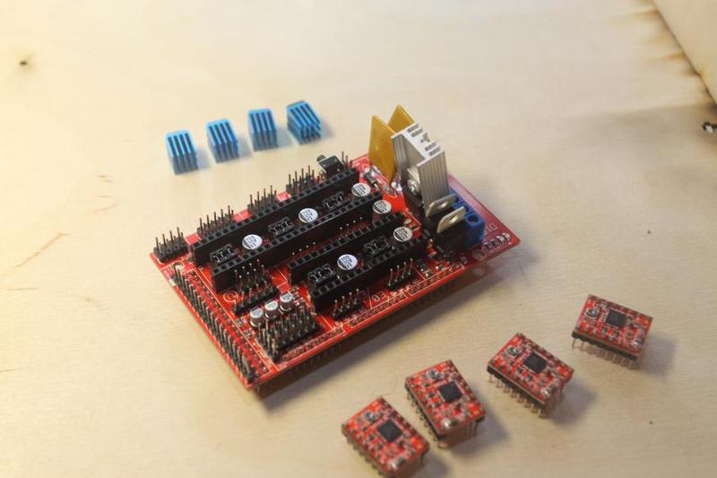
Install the stepper motors. Note the right position of the trimmer.
In our case, it’s right here:
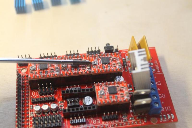
Fasten the radiators with a sheet with an adhesive material or by applying hot-melt adhesive. Thermal paste is known to work fine too.
You'll need:
Use the kind of brass couplings that can be taken from system units or other appliances, but that’s not necessary — plain screws and nuts will do.
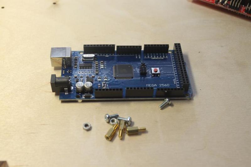
There’s a tiny flaw in the frame — if holes for Arduino are drilled like this:
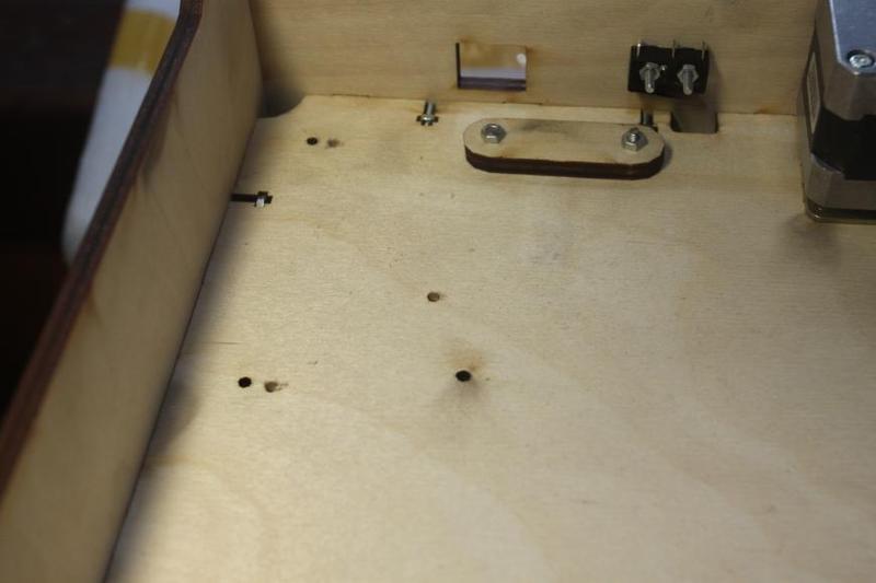
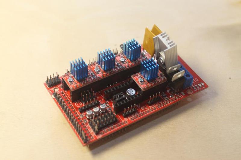
Here’s what we get:
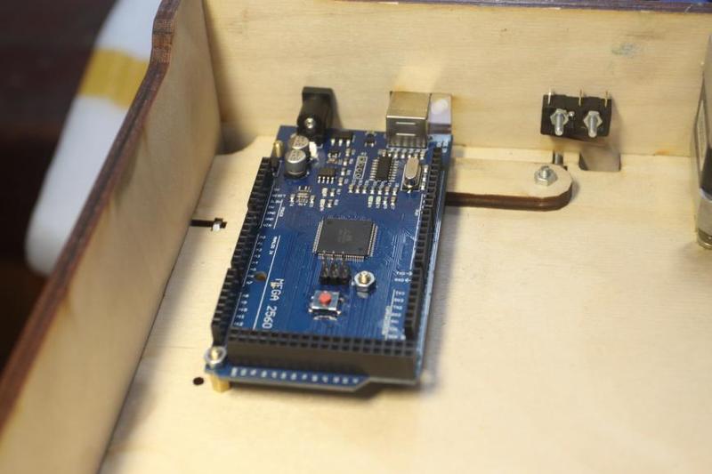
Install the RAMPS atop, taking into account the positions of all the sockets:
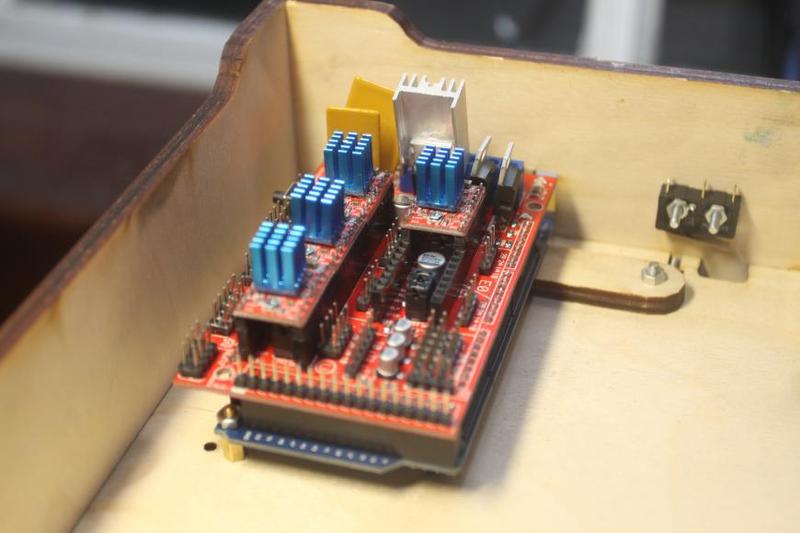
You'll need:
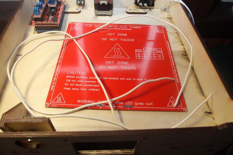
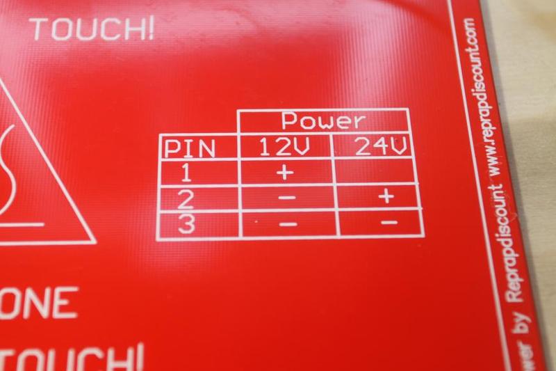
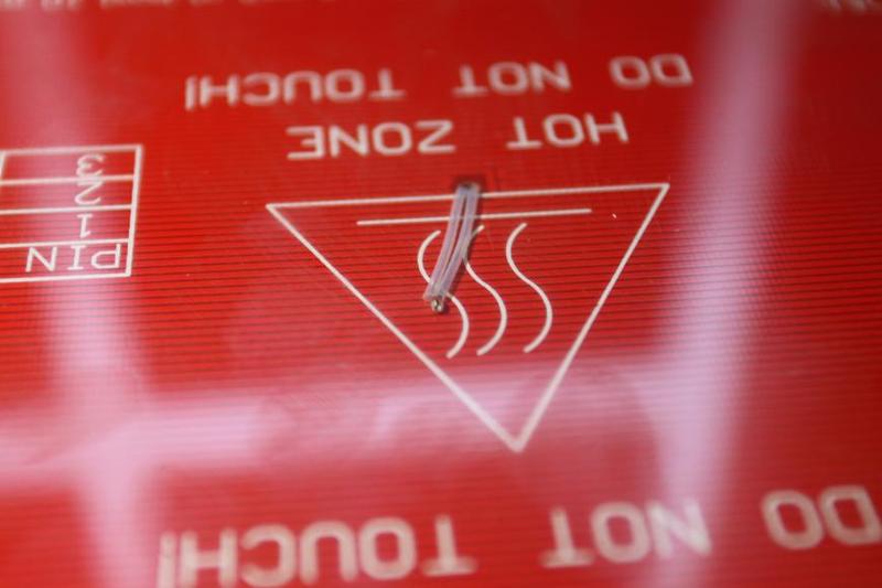
You must pay attention to the information given on the heating unit itself: in case of 12V, the negative terminal needs to be connected to contacts 2 and 3, and the positive terminal to contact 1:
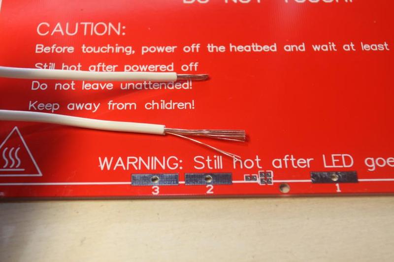
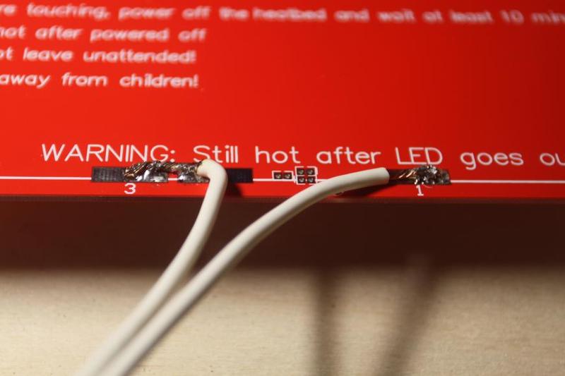
Note that there are two different sides of the heating unit: the side with the stripe and the smooth one. We recommend using it with the stripe facing up at the glass and soldering the wires to the smooth side.
We do the soldering, and here’s the result:
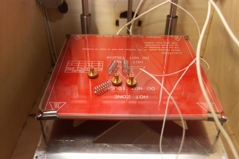
The next step is installing clamps for glass and bed calibration screws:
You'll need:
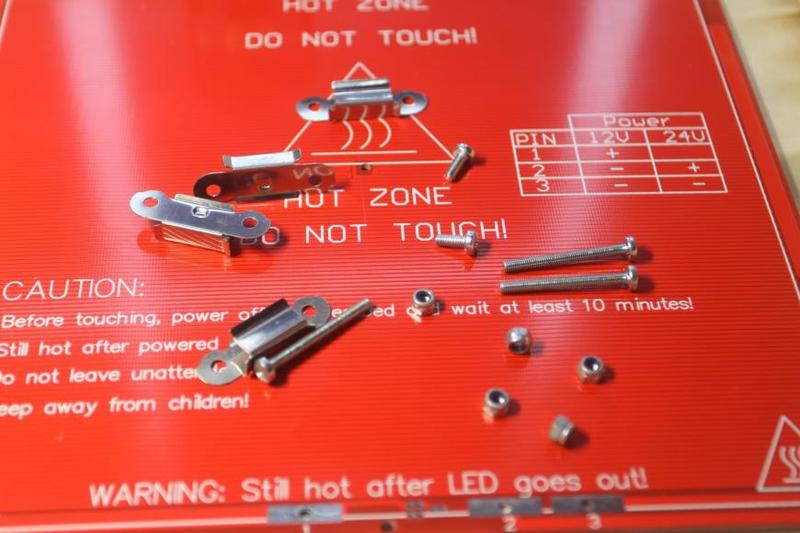
М3*30 screws are installed into the two front corners as well as midway between the contacts; we place the clamps onto the two front ones and tighten the nuts. We then install the two remaining clamps into the two remaining corners with M3*6 screws and nuts.
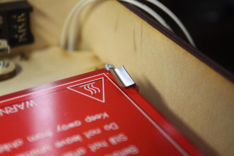
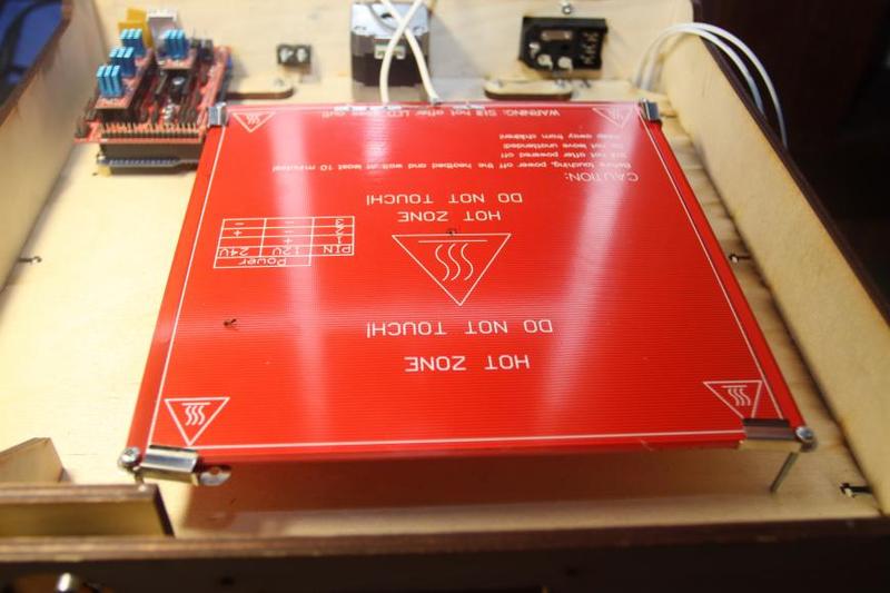
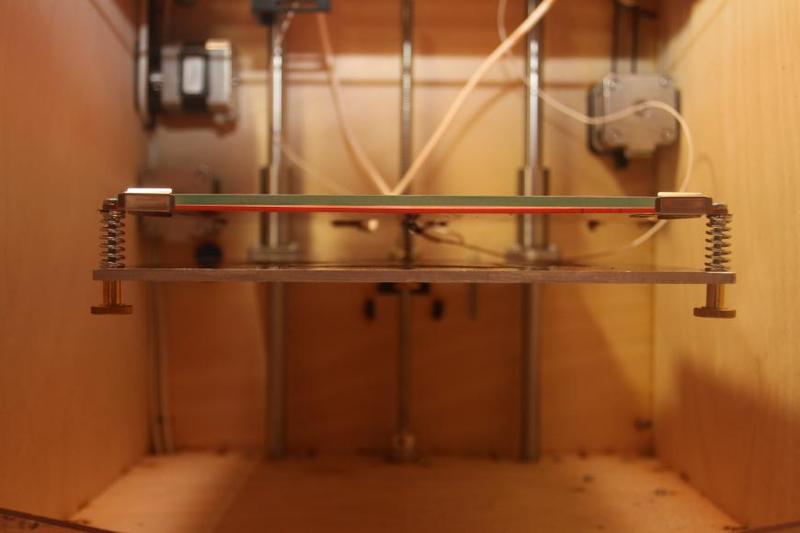
Install the glass and the bed thermistor:
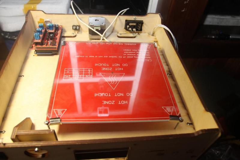
Installing the bed into the proper position:
You'll need:
Starting assembling:
And here’s the result:

You'll need:
Let’s get to the assembling:
And here’s the result:
You'll need:
We use couplings from system units, but they are to be used with M3, so in this case, the holes need to be drilled further so that they are wider.
We do the assembling, and here's the result:
You'll need:
We recommend:
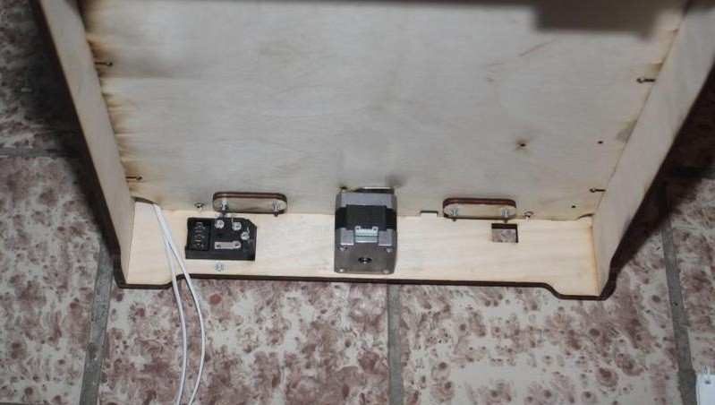
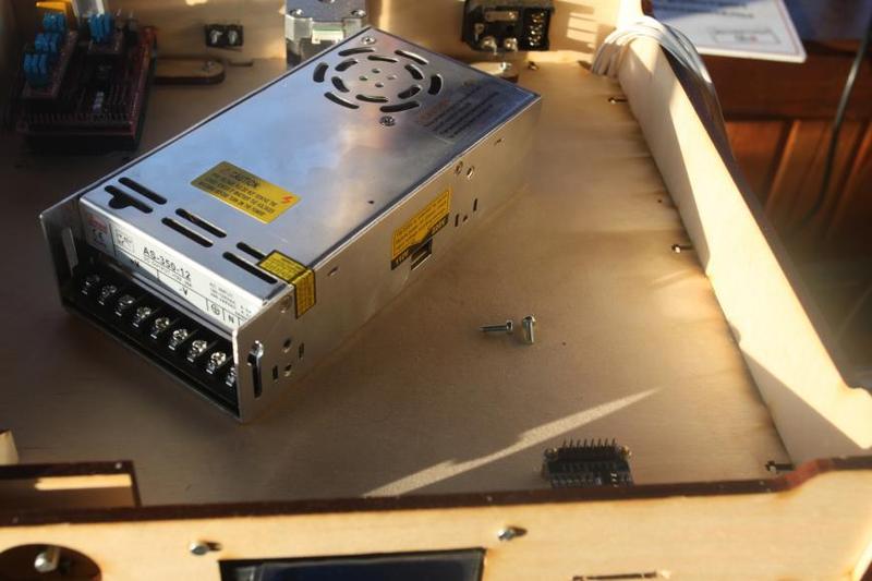
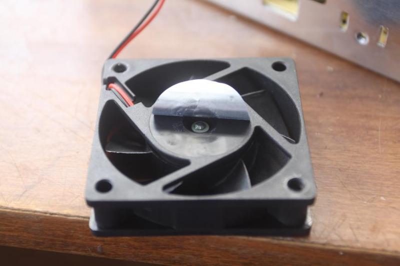
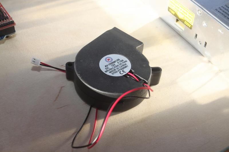
1. Disassembling and greasing the power unit fan and applying a drop of silicone oil under the sticker:
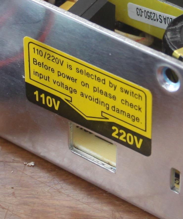
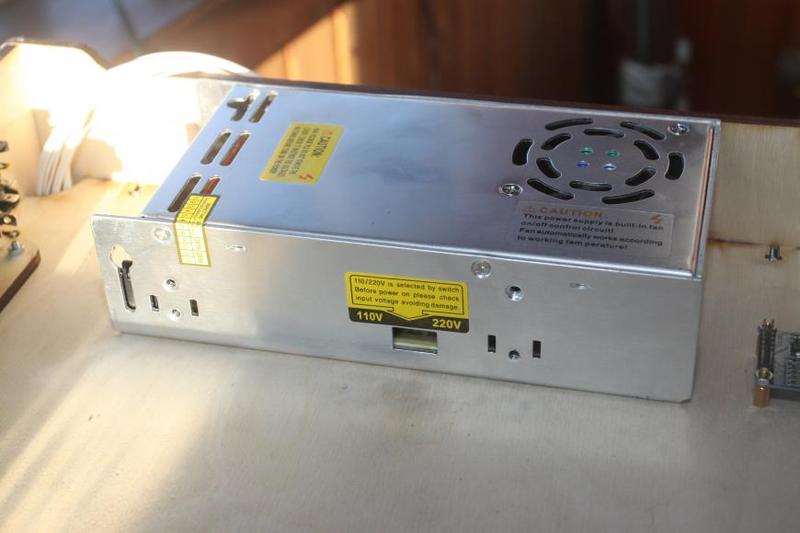
2. Ensuring that the power unit is in the 220V mode (there’s a sticker with a hole on one of its sides).
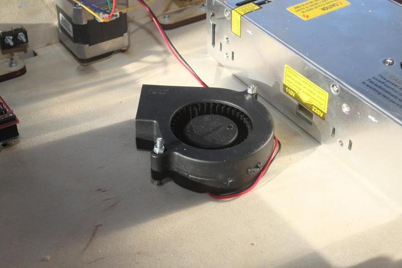
We get to assembling, and here's the result:
You'll need:
We get to assembling, and here's the result:
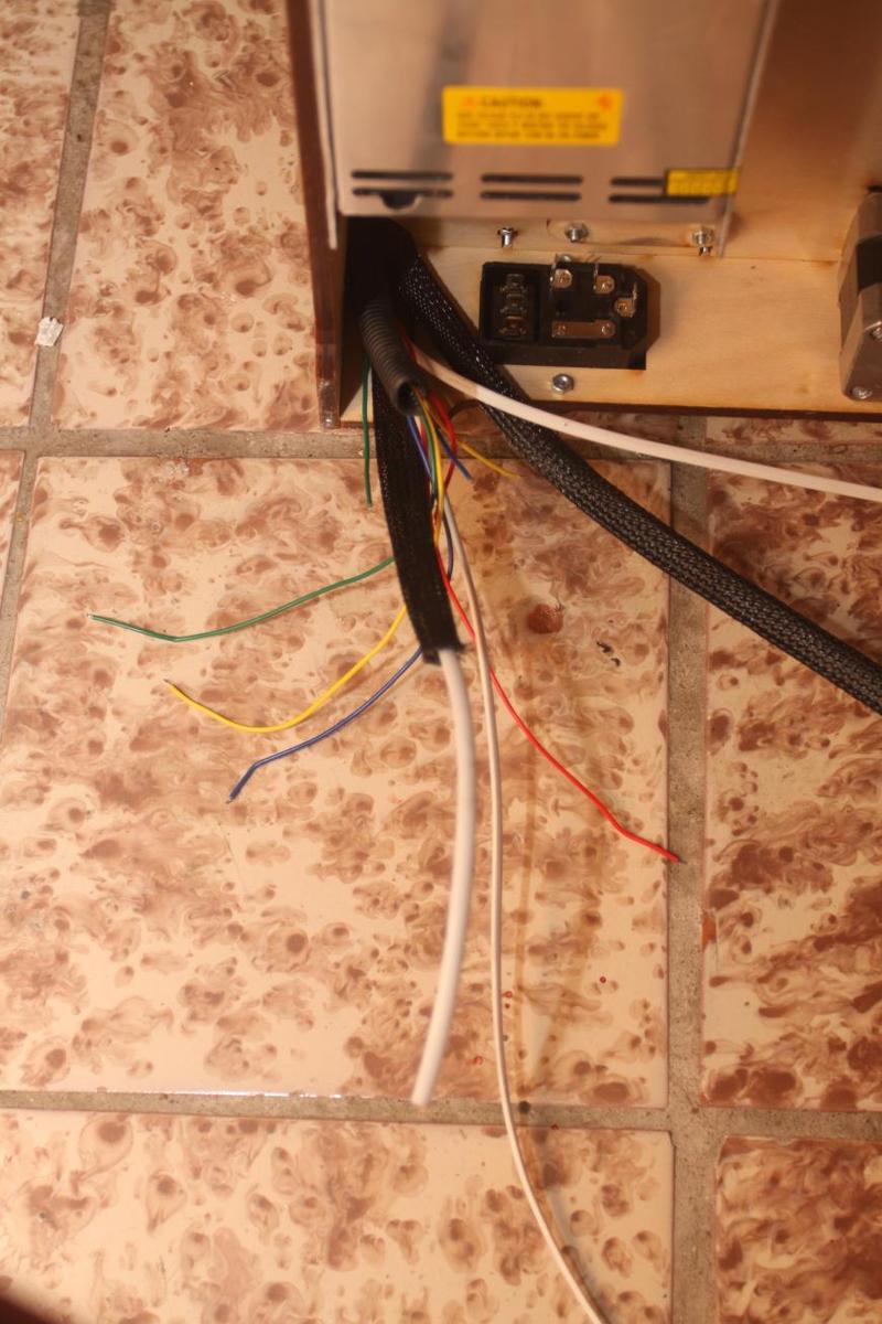
You'll need:
1. Corrugated material and/or flexible braiding for wires.

Bed wiring (heating and thermistor) are placed into flexible braiding as well.
You'll need:
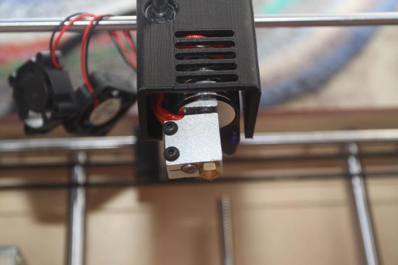
1. Print head
Or the standard е3d, ver. 6 or 5
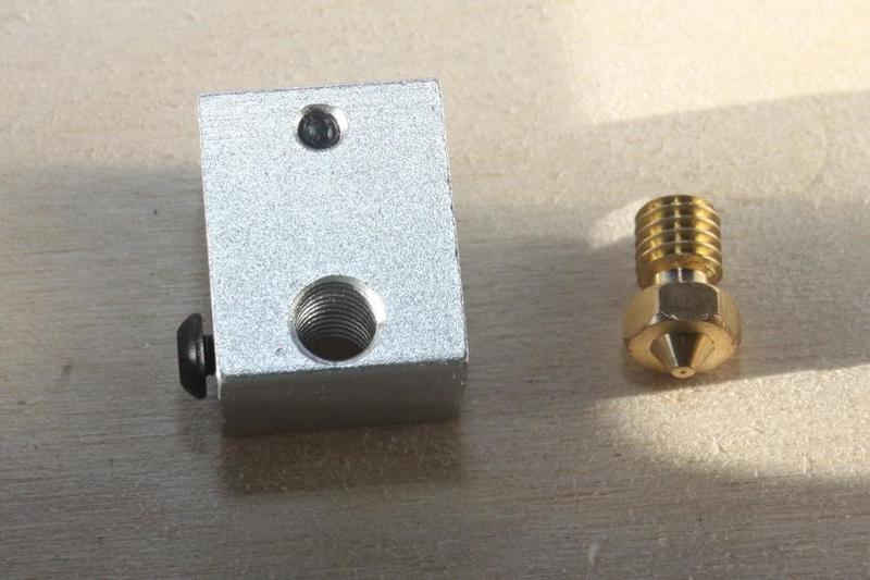
Or Volcano е3d, ver. 6 or 5
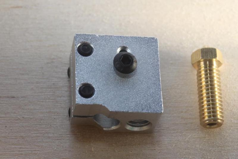
2. Thermal barrier
3. e3d radiator, ver. 5 or 6
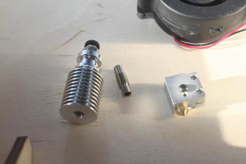
An e3d is assembled according to this instruction
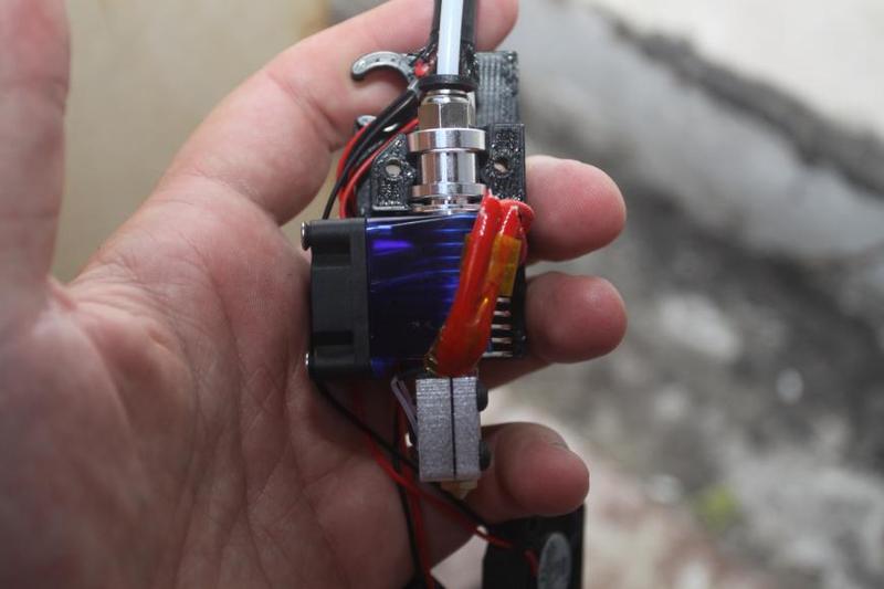
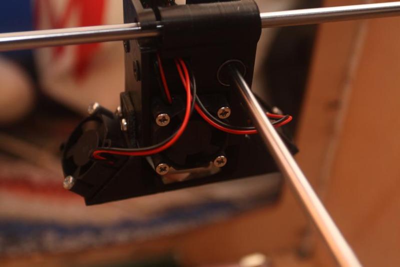
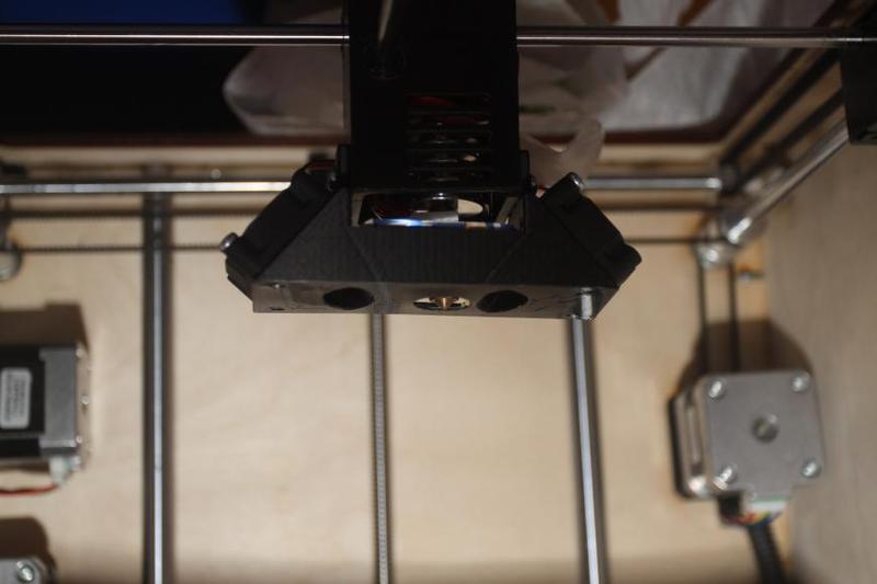
4 wires are laid from the print head, each 1.5 m long and with a cross-section of 0.22 mm2. Cooling for the print head and the print.
Wires from the ceramic heater, bed thermistor, print cooling, and the print head are placed into flexible braiding.
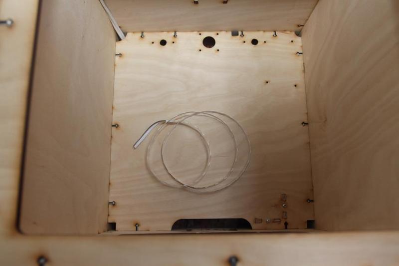
A fluoroplastic tube (Bowden), 70 cm long, is laid from the print head to the extruder.
The wires in the braiding and the Bowden tube are connected using duct tape and thus hidden.

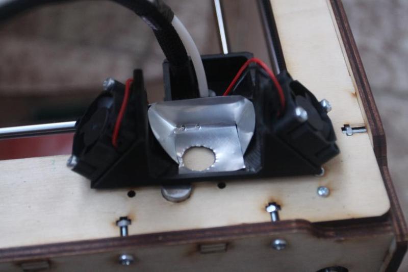
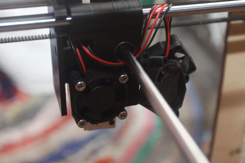
The cooling fan of the print head is soldered to one pair of the wires; two print cooling fans are soldered to the other pair, and the components are screwed to the cooling. The fans should be greased — otherwise, they will produce noise.
By the end of this part, our printer will already be fully operational.
For this part, you’ll need a multimeter, a USB cable from the Arduino Mega set, and an SD memory card.
We have to warn you that before powering the thing up, you need to check 10 times whether everything is connected correctly: when working with a multimeter, one slight mistake renders the Arduino dead. The author of the original post destroyed 3 Arduino Megas like that, one of them while calibrating the printer. So if you have any doubts, double-check everything! We have warned you!
The things that need checking first and foremost:
1. Position of the motors.
2. Whether the limit switches are connected correctly.
3. Polarity of all the wires.
4. General wiring plan for all electronic components.
Have you checked it all? 10 times? Then let’s move on:
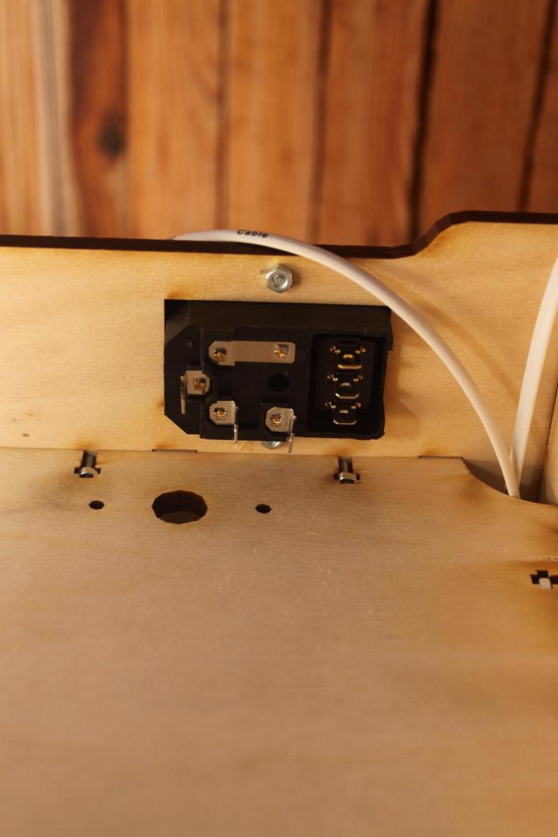
Plug the printer into an outlet, flip the switch (the one on the socket for power cord with a fuse — don’t forget to install a fuse), and the following items must switch on:
1. Fan on the power unit.
2. Cooling of RAMPS.
3. Print head radiator cooling unit.
4. Display backlight.
5. The printer backlight can be switched on and off with a switch.
Is it all working?
If not - return to the previous parts.
If yes - let's move on.
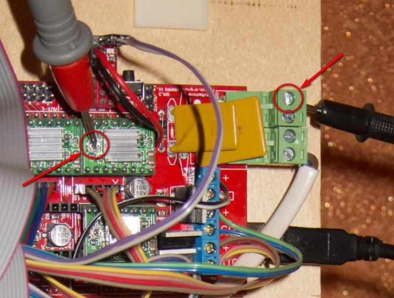
Measure the voltage with a multimeter (DC volts - V). For А4988 drivers, we can do without a multimeter, though: just sound will suffice. But we do everything by the book and set a voltage of 0.68В for all motors, with a voltage of up to 1V possible for А4988.
If you’re sure you’ve done this correctly, let’s move on:
Arduino Software can be downloaded here. This program sometimes behaves somewhat strangely: the author managed to make the 1.8.10 version work, but some of the professional peers have other versions. So, install it your our computer.
Since our Arduino is most likely no Arduino at all but a made-in-China replica with a CH341 chip in it, we also need to download the driver, here for example, and install it on our computer.
Download the Marlin firmware and unpack the archive with the firmware into a convenient folder.
Download the library – u8glib – without unpacking the archive.
Connect the printer to the computer with a USB cable, and then the driver installation takes place, resulting the new device popping up in your Device Manager:
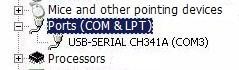
It can remember the COM number of the port into which your Arduino board is installed.
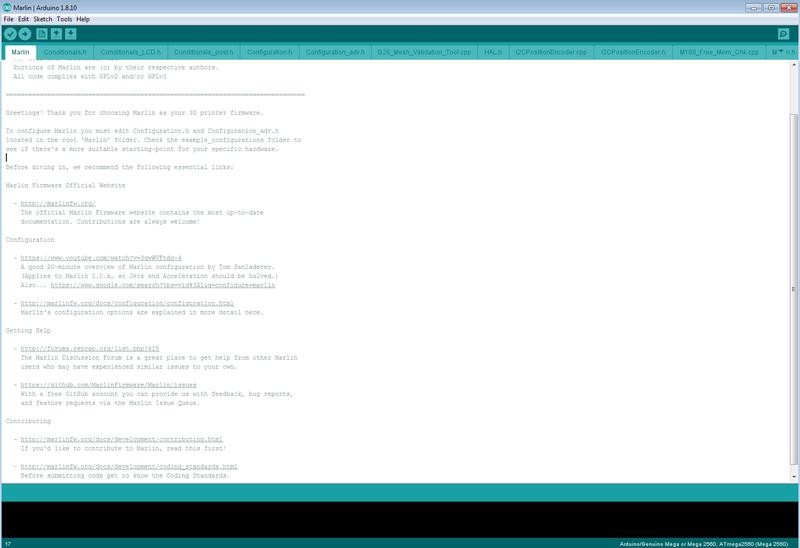
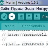
Open the file ...Marlin-RCMarlinMarlin.ino ( Windows Explorer can have it as plain Marlin, without the file extension) using Arduino Software:
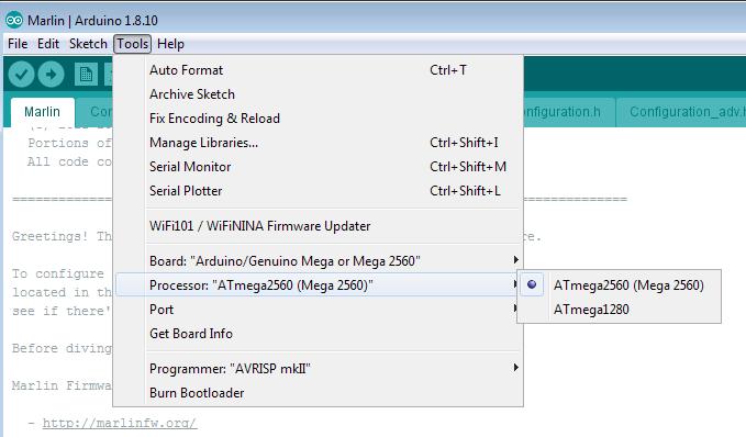
Then: Tools - Board:..., select your board, that is, Arduino/Genuino Mega or Mega 2560.
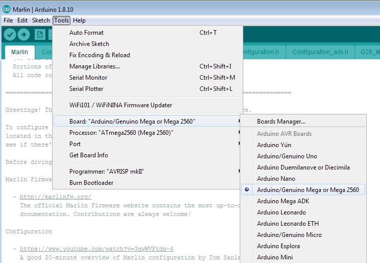
Then: Tools - Processor:... - ATmega2560(Mega 2560).
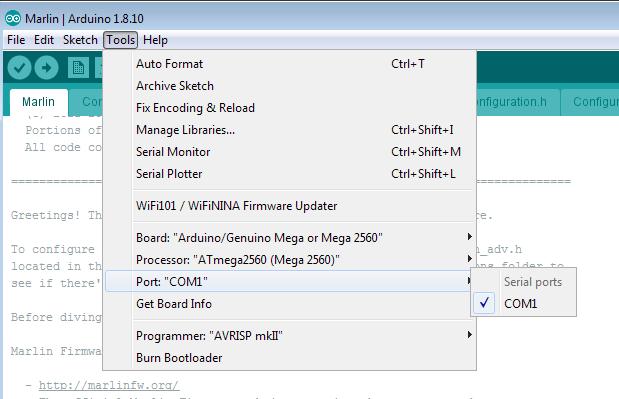
Then: Tools - Port:... - select the COM port, which our Device Manager remembered.
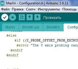
Let's move on - open the tab Configuration.h:
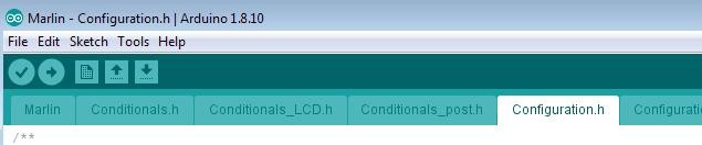
All basic settings will be adjusted in this tab.
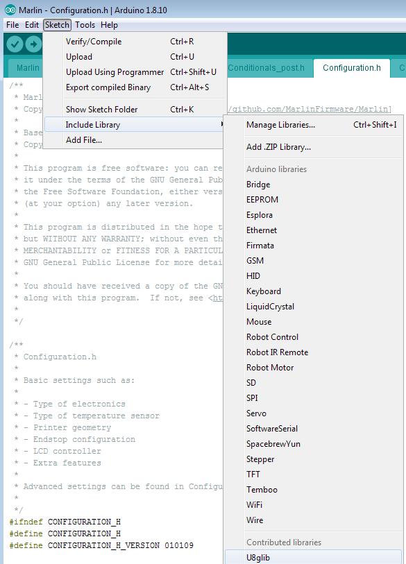
Now we need to add a library to work with our display- that is, add the u8glib, which we have already downloaded. We need to add it to our firmware.
Then: Sketch - Include Library (Add a library) - Add .ZIP Library...
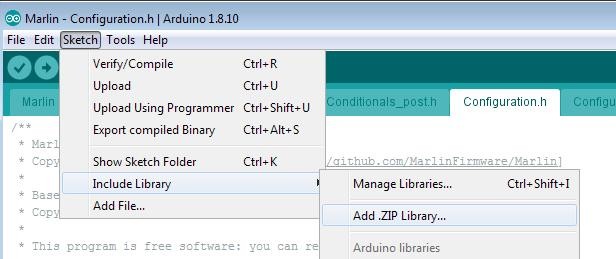
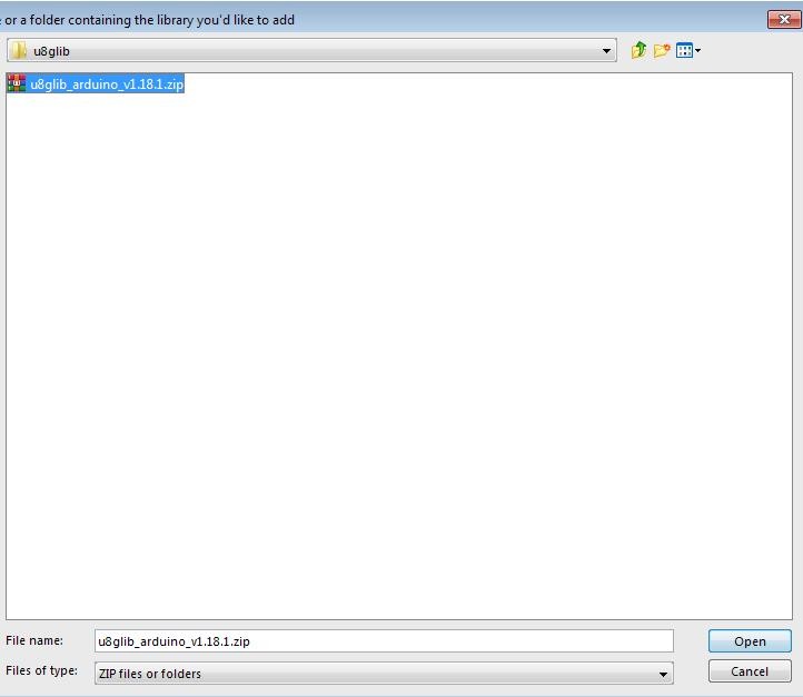
In the window that opened, we find our archive with the u8glib library, select it and press open.
Then: Sketch - Include Library (Add a library) - as we can see, the u8glib popped up at the very bottom; select it.
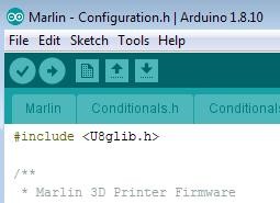
The following line appeared in our sketch:
#include
Let's calibrate the firmware now:
1. We need to select the controller of our printer - open the tab boards.h
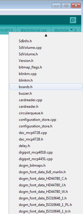
There check out the massive list of controllers Marlin firmware can already work with:
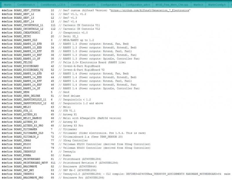
A brief reminder: we use Arduino Mega 2560 + RAMPS v 1.4, and we have a heating bed, a controlled print cooling unit, and one print head. Everyone's most likely managed to find our board by this stage:
#define BOARD_RAMPS_14_EFB 43 // RAMPS 1.4 (Power outputs: Hotend, Fan, Bed)
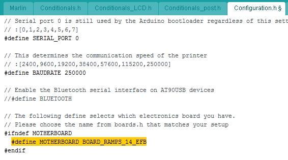
Go back to the tab Configuration.h
Search for the line where the controller must be indicated (MOTHERBOARD) and write our line there:
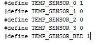
You most likely have the same ordinary made-in-China 100K thermistor. In this firmware it's marked with number 1:
// 1 is 100k thermistor - the best choice for EPCOS 100k (4.7k pullup)
Write the figures for the hotend and the bed:
Maximum and minimum temperature values can be left unchanged or adjusted according to your particular needs.
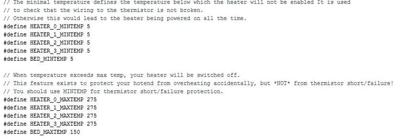
We recommend doing it only after you've been successfully printing with your device for two hours.
The algorithm is as follows: we need to access the printer through the Pronterface software
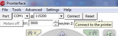
...and use this command:
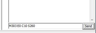
Where M303 is the calibration command, E0 is the hotend, C10 is the number of heating-cooling cycles, and S260 is the standard operating temperature of the nozzle.
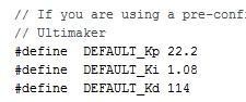
The printer makes 10 hotend heating cycles and then displays the values of Kp, Ki, and Kd. We put these numbers into the firmware:
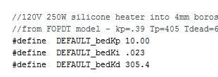
The same goes for the bed, with the command being:
M303 E-1 C10 S110
Where E-1 is the bed, S110 is the standard bed heating temperature.
Since bed heating takes a long time, an error may appear as a result of a timeout - in this case, just restart the command.
Put the resulting numbers into the firmware:
A brief reminder, we have:
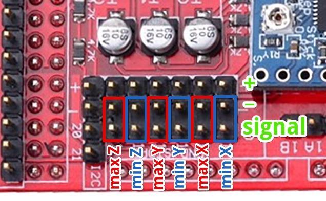
Accordingly, we comment on(//)/uncomment the following lines:
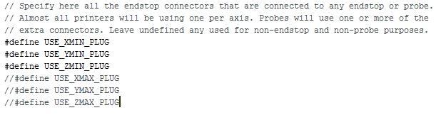
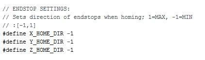
We also change the direction of the “home” position according to the position of the limit switches:
In our case, the resulting figures are quite good: 200x200x190 mm.
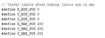
Your figures can be slightly different, but this will be known later after much experimentation.
This information is obtained through experimentation; for now, use the default values.

We need to find out how many steps our printer makes per distance unit (1 mm in our case) along each axis.
We’re using a motor that makes 200 steps per turn, и and we can divide this step into 16 micro-steps.
Then, in the X- and Y-axes we have the belt motor, with the step of each tooth amounting to 2 mm and the pulley having 20 teeth.
Thus, in one turn our motor makes 200x16 = 3 200 steps and covers with these 3 200 steps a distance of 20x2 = 40 mm.
Subsequently, in order for the printer to pass 1 mm, 3200/40 = 80 steps are required (this number is the same for the X- and Y-axes).
A trapezoidal screw is installed on the Z-axis, with the value of one step that can vary depending on the type you bought. For instance, 8 mm per one full turn, meaning that our printer passes 8 mm during the time of one Z-axis screw turn and makes the same 3 200 steps to this end — however, splitting (with the use of jumpers) and ⅛ can be employed for the acceleration of the Z-axis.
So, for the printer to pass 1 mm in the Z-axis, it needs to make 3 200/8 = 400 steps.
Extruder feeding. To learn how much plastic is fed by our extruder, we need to calculate the circle perimeter: school geometry reminds us that the circle perimeter equals 2 x the number π x circle radius or the number π x circle diameter. Now we don’t need any great accuracy (we’ll calibrate that more precisely a bit later). The diameter is approximately 5.8 mm, so per 3200 steps or one turn our extruder feeds 3.1415x5.8 = 18.2207 mm of the filament, and to feed 1 mm it needs 3 200 / 18.2207 = 175.624 steps — we round that to an integer number of steps, that is 176.
Put the resulting figures into the firmware:

here: X, Y, Z (in the right order), the extruder.
For now, we left these parameters unchanged — we’ll return to them later, during the more precise calibration:

We uncomment (remove the double slash // from) the lines:
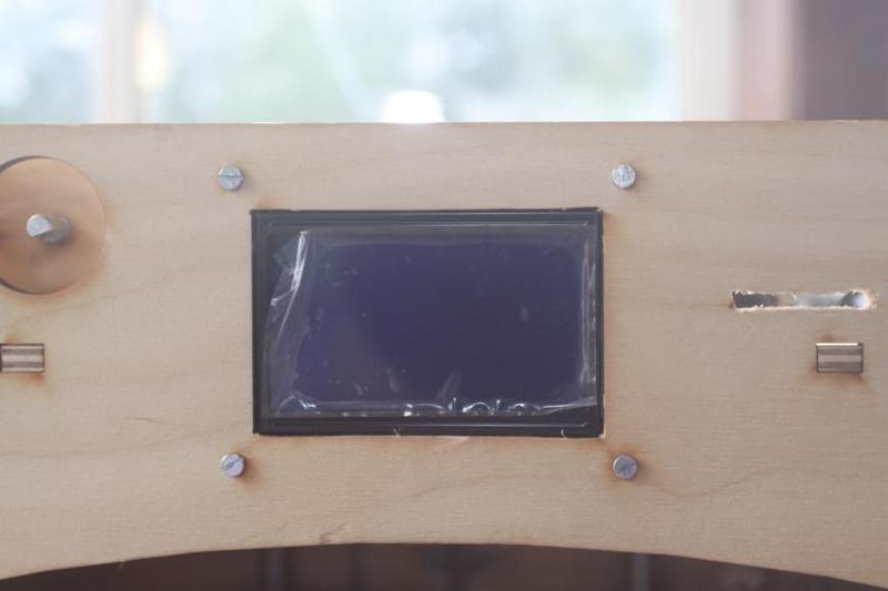
#define ULTRA_LCD
#define DOGLCD
#define SDSUPPORT
#define ULTIPANEL
#define REPRAP_DISCOUNT_FULL_GRAPHIC_SMART_CONTROLLER
To this end, we need to uncomment the line:
//#define CUSTOM_MACHINE_NAME ‘Kevin’
All the basic firmware settings have now been dealt with. Check what you got by pressing “Test”:
And upload it by pressing “Upload”:
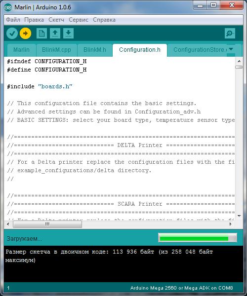
After that, the printer will restart and display various parameters.
1. correct direction of axial movement.
The way it’s supposed to be:
X-axis - 0 to the left (or minus), 200 to the right (or plus)
Y-axis - 0 facing you (or minus), 200 to the other side (or plus)
Z-axis - 0 up (or minus), 190 down (or plus)
extruder - plus for feeding filament, minus for retracting filament
If everything’s alright, let’s move on. If not, you should change the parameters: true to false or false to true - the parameter is only changed where necessary (where the axial movement is wrong):
#define INVERT_X_DIR false
#define INVERT_Y_DIR true
#define INVERT_Z_DIR false
#define INVERT_E0_DIR false
Compile it, renew the firmware again and check whether everything’s right. If so, let's move on.
2. The performance of limit switches:
Set up the carriage and the bed in such a way that the limit switches aren’t under any pressure.
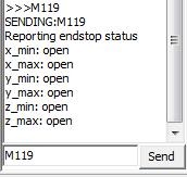
In Pronterface use the command M119.
The result will look something like this:
or like this
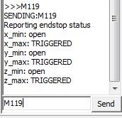
the way it’s supposed to be:
x_min: TRIGGERED
x_max: open
y_min: open
y_max: TRIGGERED
z_min: open
z_max: TRIGGERED
or
x_min: TRIGGERED
y_max: TRIGGERED
z_max: TRIGGERED
After that, consecutively set the carriage and the bed to the home position for each axis and check whether the limit switch worked correctly with the command M119:
For each of the axes that were involved, open must show; it’s better to perform this separately, to ensure that the travel switches are connected correctly. The resulting image is supposed to look like that:
or
x_min: open
y_max: open
z_max: open
This only applies for properly closed contacts, and if you use properly open ones, then everything will happen the other way around: if the limit switch didn't work, you will get open, and if it worked - TRIGGERED.
If something's wrong, the highest possibility is that you made a mistake in adjusting the previous setting that dealt with limit switches — or did something wrong while connecting them. Go back and check that.
3. Correct movement to the home position.
Give the printer the return-to-home-position command — that can be done through the printer menu or computer software.
The carriage should move to the left and away from you, and the bed should travel down.
Is everything done correctly? Let's move on then. Are there some difficulties? Go back to checking the firmware.
4. Defining movement values:
Here, we’ll have to experiment quite a lot; define the values for all 3 axes with a ruler to type them into the firmware:
5. Checking the filament feeding system:
Take a ruler, measure off 10-20-30 cm of filament, mark the results and give the printer the command to extrude 10-20-30 cm of filament. Then check the accuracy and adjust the firmware according to the numbers.
6. The distance between the bed and the nozzle.
First, we need to apply a coating to the bed to get good adhesion. The author prefers using a glue stick (3M Skotch, UHU). We apply the adhesive to cold, clean, dry glass, and then we can heat the bed.
Heat the bed and the nozzle up to the operating temperature (110/250) and put the bed into point 0 — and then adjust it through three points (the ones where the leveling knobs are located)
Using knobs we adjust the space in such a way that a sheet of paper is pressed against the bed by the nozzle, but with us being able to draw it out without ripping it. We need to ensure that the same distance is observed in any location of the printer. To this end, twofold leveling of the bed with 3 points is enough.
Some of the parameters can be changed through EEPROM, which can be done using Repetier-Host or using commands in Pronterface.
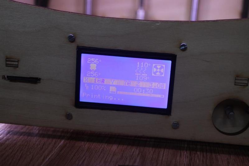
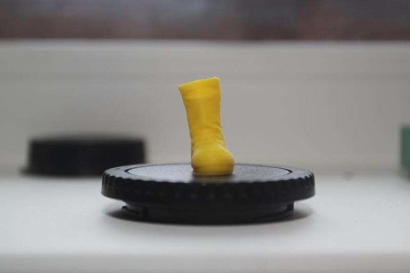
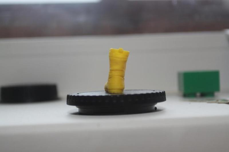
Let’s see such a printer can do:
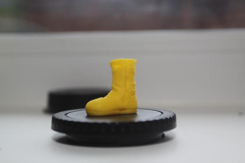
Another print, but of a higher quality and printed with a better material:
Update your browser to view this website correctly. Update my browser now
Write a comment