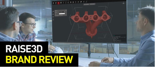
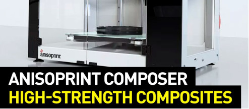
Anisoprint specializes in making interesting 3D printer models capable of printing parts reinforced with continuous carbon- or basalt-fiber. Most reviews and webinars about the company’s printers come down to impressive figures and descriptions of the technology’s incredible possibilities, but we would like to review the following printer from the end user’s perspective.
This is Top 3D Shop, and today we are going to talk about the specifics of use, limitations, and peculiarities of the Anisoprint Composer A4 3D printer without boring you with a large number of charts, formulas, and terminology.
Isotropic materials have the same mechanical properties in all directions, regardless of the load angle. Anisotropic materials, on the contrary, are characterized by different properties in different directions. For example, carbon and basalt fibers feature very high tensile strength along the fibers, but it takes much less force to break them across.
It looks like anisotropy of the material could be considered a disadvantage. But with the correct load calculation and the appropriate algorithm for laying the fibers, it is possible to obtain lightest parts with the strength concentrated in the proper areas and maintained at the corresponding load angles.
In recent years, so-called composite, or more correctly, filled filaments, have become popular in 3D printing. They are two-component materials consisting of thermoplastic and carbon- or glass-fiber filler. Such filaments are stronger, stiffer, and show less shrinkage than basic thermoplastics. But carbon and glass fibers are added to such filaments in a milled form. Thus, one of the most useful properties of the fibers, namely the highest tensile strength, is almost totally lost in filled filaments.
Composite materials made of continuous fibers have been utilized in manufacturing for quite a long time. They are a kind of fabric with carbon or basalt fiber being used instead of threads. The fiber can be either one-directional or laid at different angles in several layers. Such materials naturally possess good strength properties, but, on the other hand, they have their drawbacks as well.
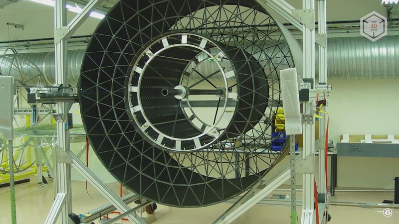
In addition, there is a way to create so-called mesh structures made of continuous fibers. Such a method, with proper load calculations, makes it possible to create more durable, still several times lighter in weight, parts, compared to similar aluminum models, for example. Such use of fibers allows making the best out of anisotropy.
Based on their experience with such types of carbon and basalt fiber laying, Anisoprint engineers created their proprietary 3D printing technology, which they call anisoprinting.
Those following the development of additive manufacturing long enough are aware that a similar technology has already been used by the Markforged company, and they are really much alike. However, there are a few noteworthy differences.
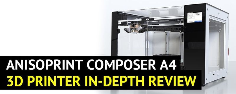
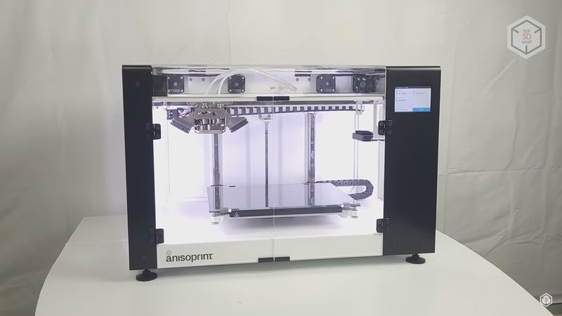
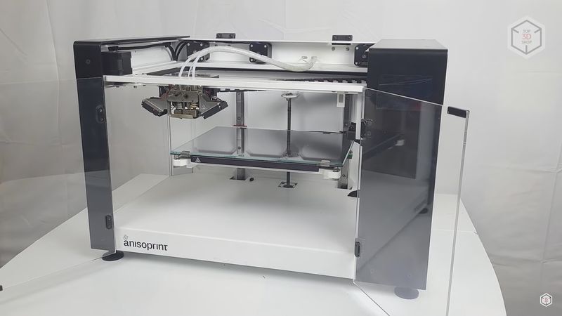
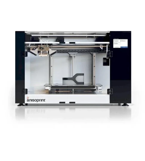
Let’s take a closer look at the printer. We have the most compact model of Anisoprint 3D printers — that is the Composer A4.
As long as Anisoprint is constantly refining and improving their printer models, some parts may appear to be slightly different from what is being produced at the moment. However, the operation principle and basic idea remain the same.
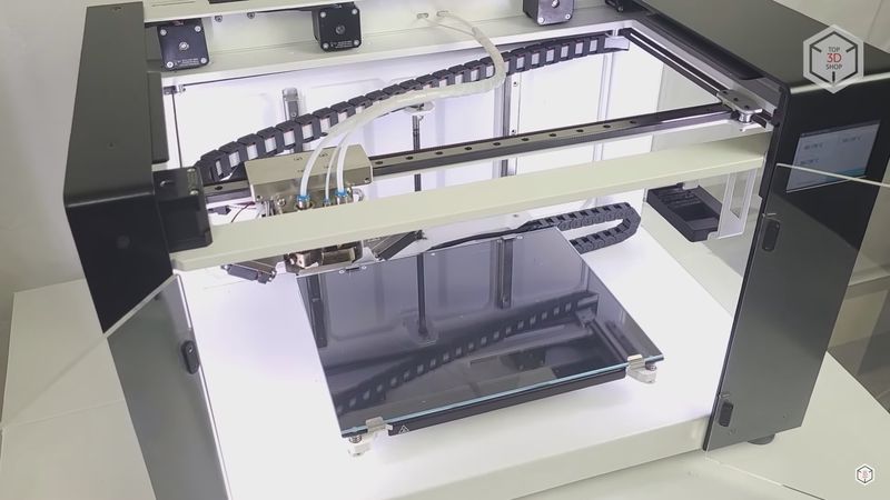
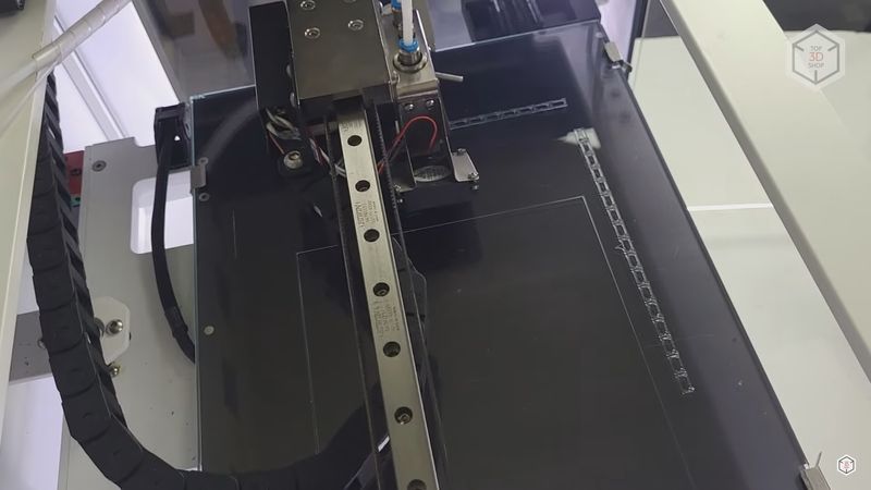
The design of the Composer A4 does not differ much from most 3D printers we are used to. The build area is 297 x 210 x 140 mm.
The frame is made of 8 mm aluminum, which gives the printer a large margin of safety, the device feels very reliable.
The printer is lined with acrylic sheeting. It has two doors with magnetic locks at the front. On top of the machine is a hinged cover. It can be opened when printing low-melting materials to avoid overheating of the plastic. When printing with high-temperature filaments prone to shrinkage, the top cover and front doors can be closed to create a passive heated chamber. In the right top corner at the back, there is an exhaust fan that automatically turns on when the temperature inside reaches 60 °C.
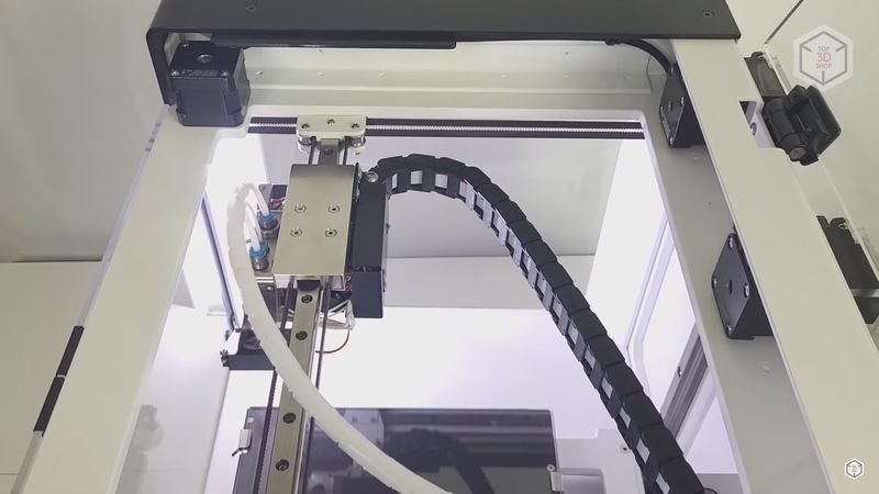
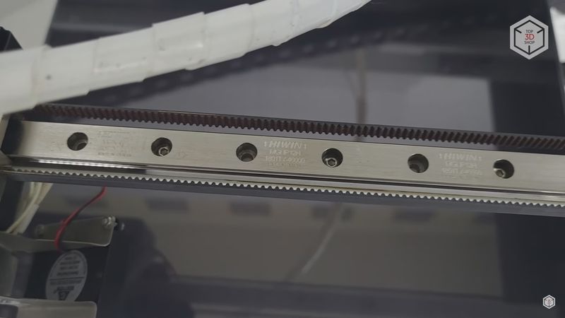
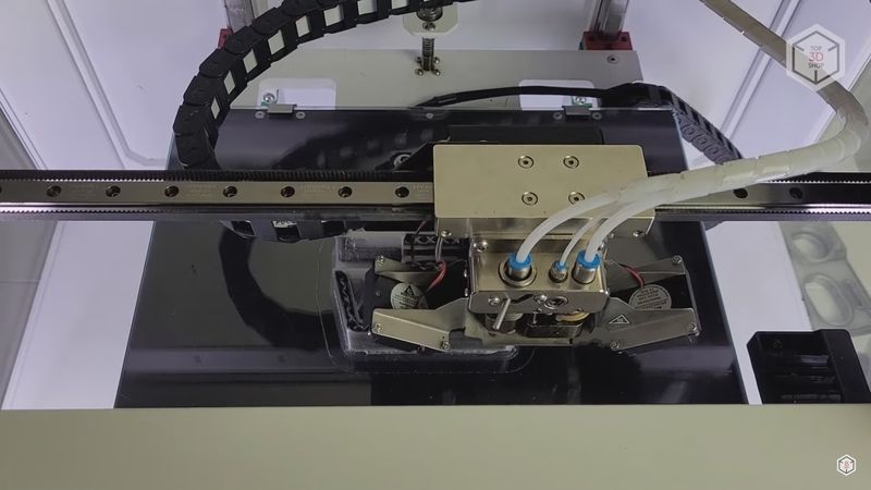
The kinematic scheme here is classic CoreXY. The print head is moved with two long 8 mm belts produced by the Gates company. The X and Y axes move along high-quality 12 mm Hiwin rails. They are driven by Nema 17 stepper motors mounted at the front of the printer.
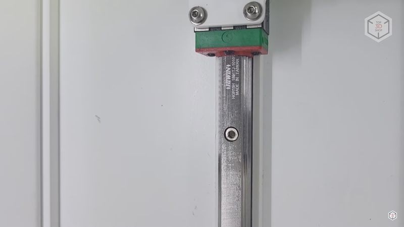
The Z axis runs on two 15 mm Hiwin rails, and it is driven by a screw motor. That is, a trapezoidal single-thread screw comes out directly of the motor, without any couplings. The motor itself is located inside the lower compartment.
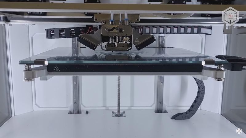
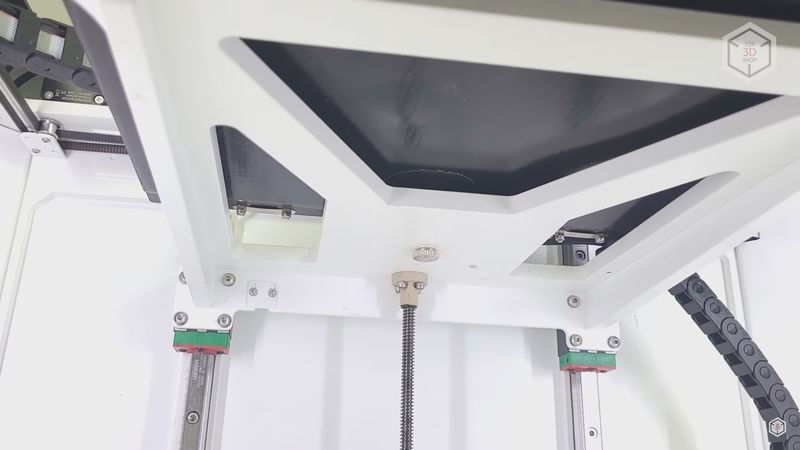
The print bed is cantilevered, which means it is attached to one side. Nevertheless, the bed frame is massive and solid, so that the bed does not sway during printing.
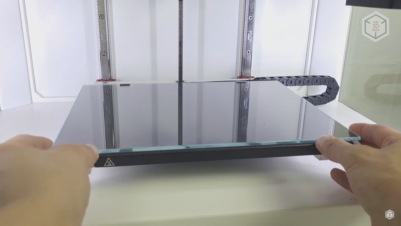
It is covered with a glass build plate which is held in place with two fixed brackets in the back and two hinged ones in the front. The glass can be easily removed and put back on. The maximum print bed temperature is 120 °C. Calibration is done manually by three points using a software assistant, but more on that a bit later.
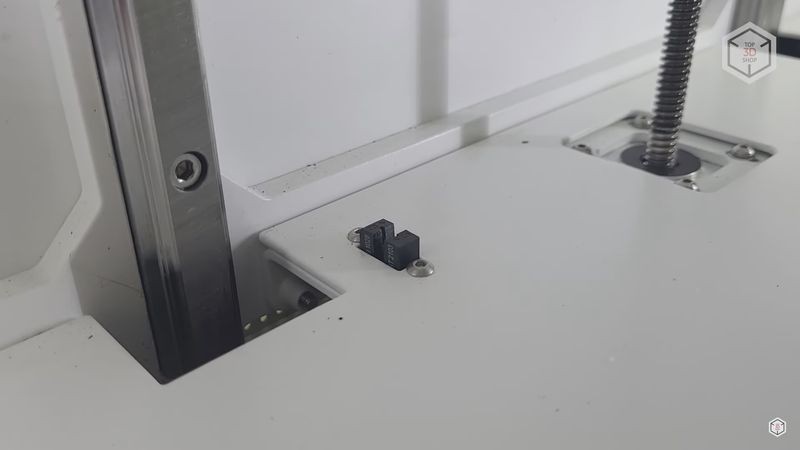
All of the printer’s endstops are optical, which gives high axis positioning accuracy before printing.
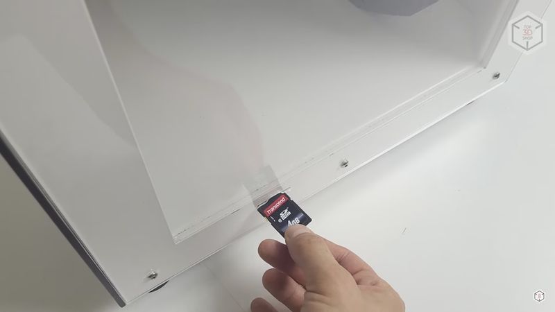
You can print from a full-size SD card or via a USB cable. The port for an SD card is on the right side of the printer.
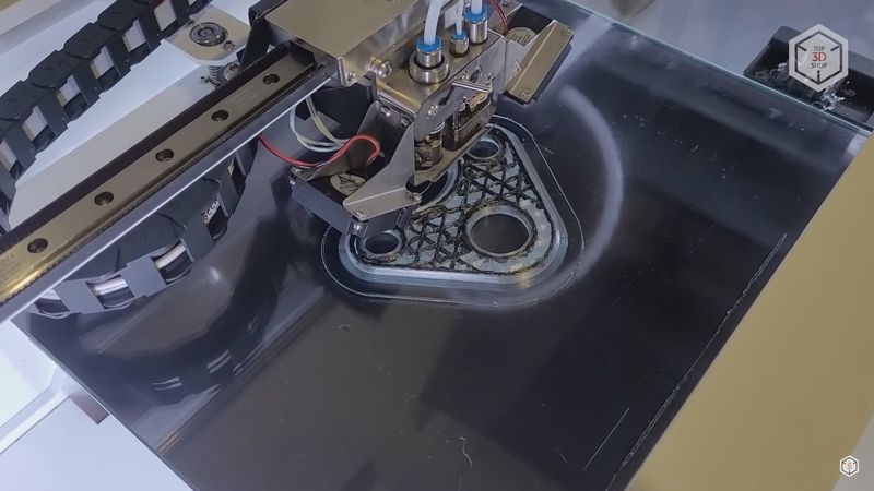
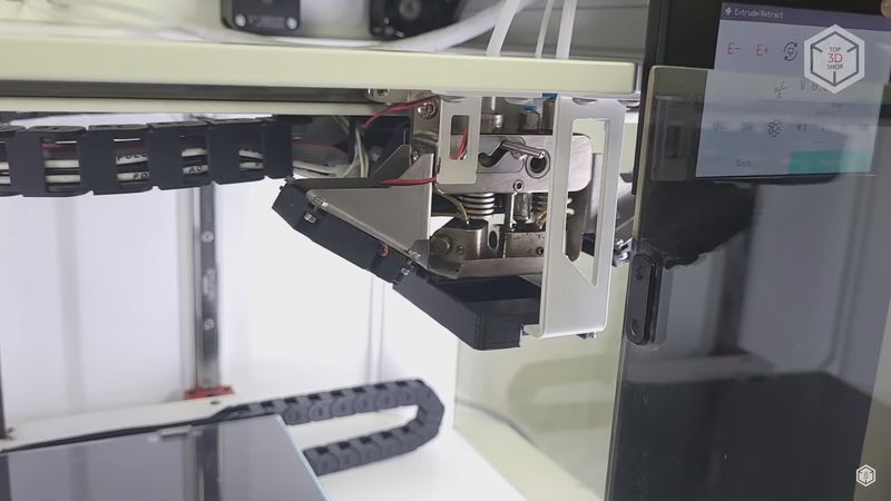
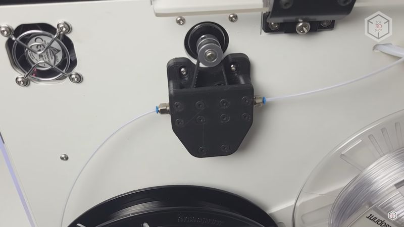
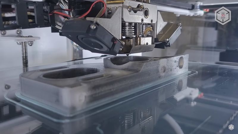
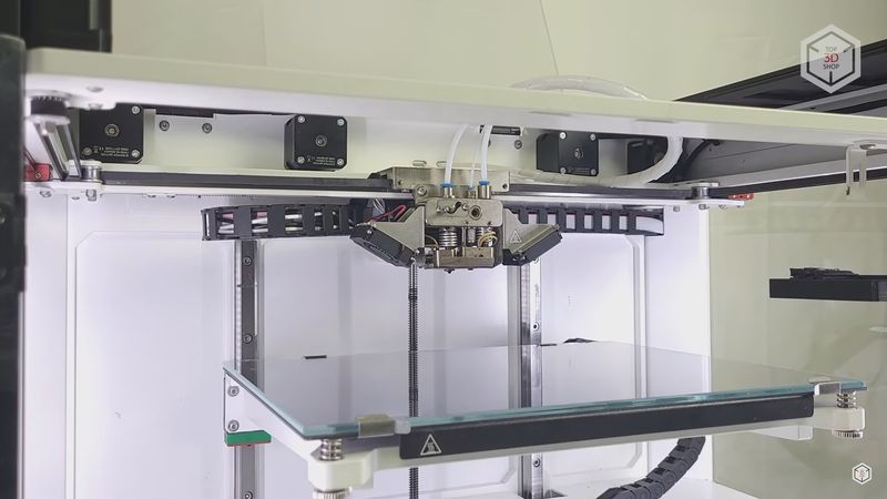
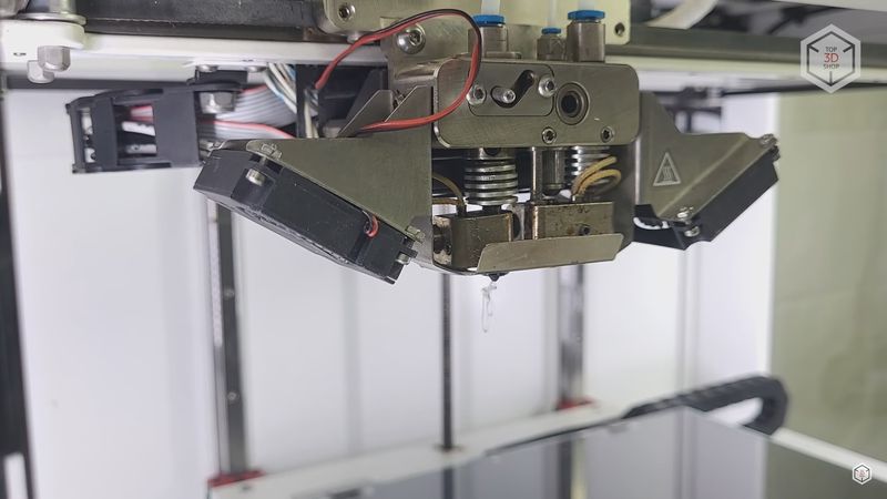
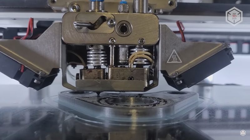
And finally we get to the most interesting part, the extruder. To be more precise, there are two extruders here. On the left there is a usual hotend with a hardened 0.4 mm nozzle which can be changed to a 0.6 one.
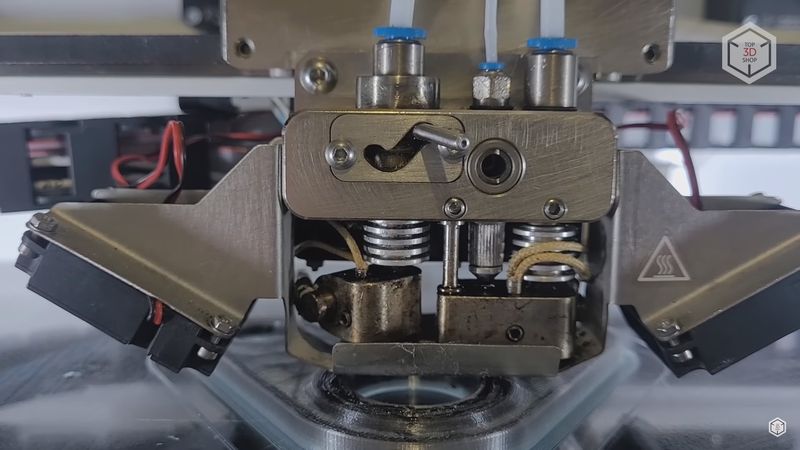
The nozzle type here is V6. This hotend is utilized for basic or filled filament printing. It can be used alone, when printing standard polymer parts, or together with a composite hotend to print fiber reinforced models.
The left hotend has a lifting mechanism so as not to interfere with fiber printing. The mechanism is quite simple, but due to that it is very reliable.
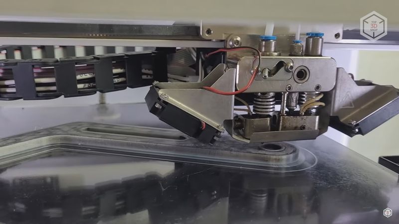
There are no servos or other motors used to switch hotends. The print head travels to a special projection on the right, which moves a lever in a V-shaped notch. While moving from left to right, the hotend goes down; and moving from right to left, it goes up.
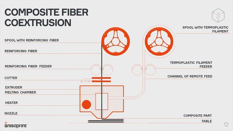
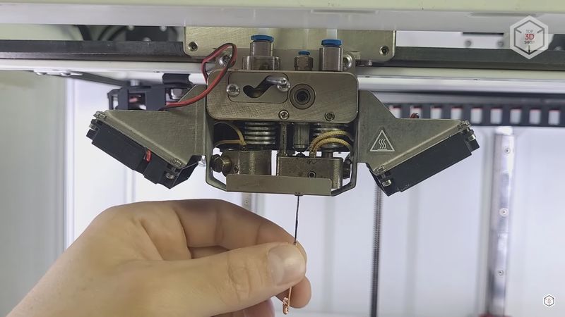
The right composite extruder is developed in-house by Anisoprint. It has a special nozzle with a diameter of 0.8 mm. The reinforcing carbon or basalt fiber is fed into the hotend from the top. The polymer is fed into the same hotend from the right side, and then it comes to a special compartment in the way of the fiber. Passing through this compartment, the fiber collects a small amount of plastic and is extruded on the part. This is necessary to ensure proper adhesion with the previous layer.
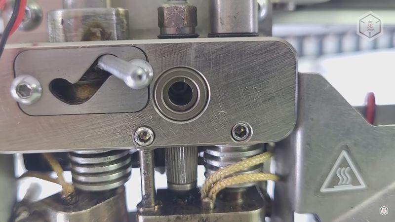
On the top of the hotend is a fiber cutting mechanism. It is a rotary knife, which is driven by a servomotor hidden inside the print head. Whenever it is necessary to switch from one hotend to the other, shortly before that the knife turns, cutting off the fiber. After that the print head travels a certain distance to allow the remaining fiber to be extruded on the part; then you can make the transfer or switch the hotend.
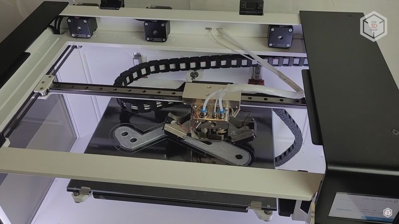
The print area is cooled by two 4010 turbine fans located on both sides. To prevent the fans from blowing on the heating units, there is a metal barrier at the bottom.
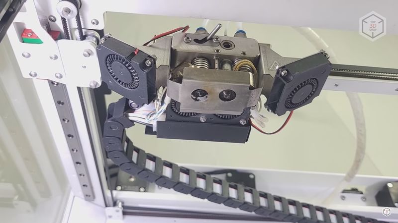
Two 4010 fans are also used to cool the heatsinks of the hotends. They are located in the back, and turn on automatically when the temperature of the hotends reaches 60 degrees. All the printer’s fans are manufactured by the GDSTime company. They are pretty quiet and do not produce any tangible vibrations.
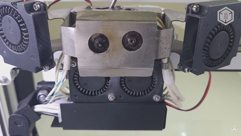
To make sure that after downtime the hotends are not clogged with leaked polymer that can spoil the model, there is a small part on the right designed to clean the hotends and collect the remnant plastic.
On the back of the print head you can find a distribution board. The wires from the sensors and heaters are connected to the board, making it easy to replace damaged elements if necessary. The wires from the board are arranged in a cable chain. It is worth mentioning that all printer wires are neatly routed and hidden, so nothing dangles and spoils the look.
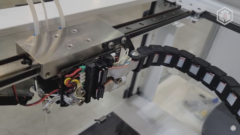
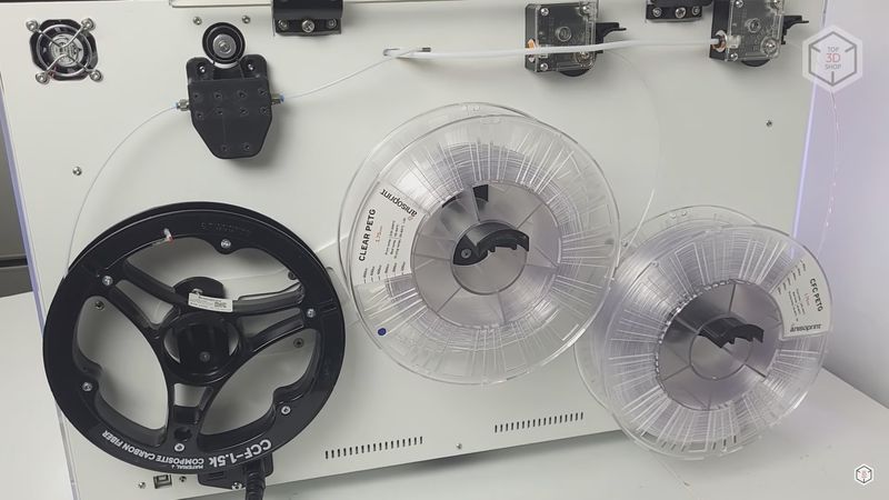
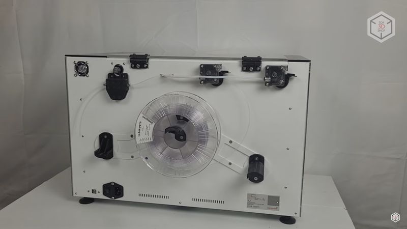
Both printer extruders are Bowden-type; the feeding mechanisms with motors are placed on the back wall, and both polymer and fiber are fed through teflon tubes.
This model uses Titan-type geared feeders for plastic. For the fiber, Anisoprint has designed a proprietary feeder. It uses two small circular adjacent belts. The construction allows the fiber to be fed without slipping, and the belts do not damage it while moving.
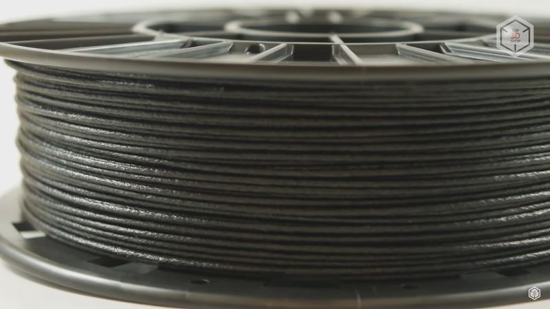
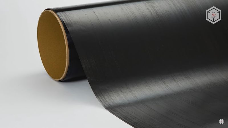
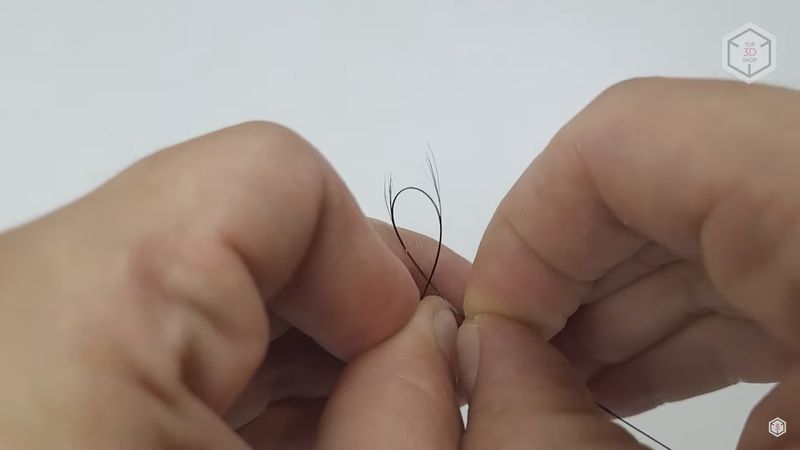
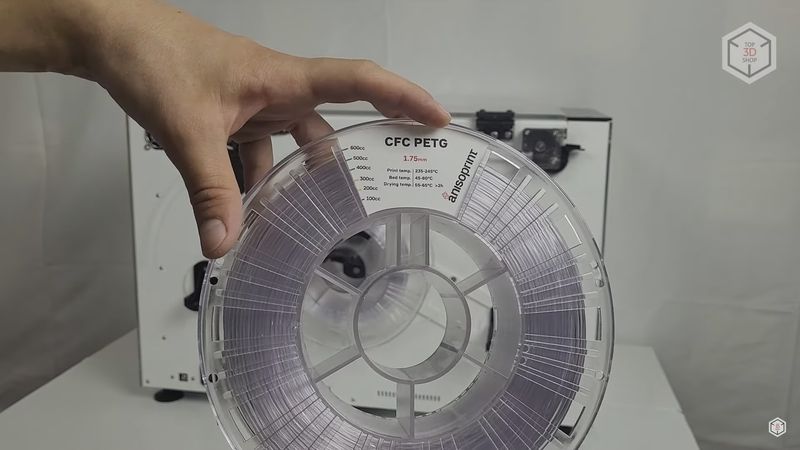
Now, what is this fiber all about? To begin with, it looks like a solid string with a diameter of about 0.36 mm. But in fact it is a bunch of very thin fibers, carbon in this particular case, impregnated with a special resin. This provides the string’s uniformity and ensures that it does not split when being fed and can be accurately extruded while printing. The manufacturer strongly recommends the use of Anisoprint proprietary fiber, made with their patented technology. You can, however, give a try to third-party fibers, but this can lead to serious extruder clogs.
For the auxiliary plastic that is used along with the fiber, as well as for the left hotend, you are free to use any filament types by different manufacturers.
This is one of the differences between the technologies used by Anisoprint and Markforged. The latter also utilizes the prepared fiber, but it is directly impregnated with a thermoplastic, usually nylon. The composite hotend feeds and immediately fuses it. For this reason, you have certain limitations on the materials compatibility. As a consequence, with Markforged you are not only restricted to the use of the proprietary fiber, but also the plastic for the other hotend can only be selected from a small suggested list, as the slicer limits your choice of settings to a great extent.
Certainly, Anisoprint also recommends using plastic and fiber tested by the company’s engineers. In this case you are more likely to get the desired results. But potentially, you have the opportunity to experiment with the printer and both plastic and fiber materials, as long as they are compatible with the hotend design. The Aura slicer with an open license allows you to adjust the printing parameters very precisely, which gives you room for experimenting, albeit at your own risk.
In addition, the composite extruder construction and the system of co-extrusion of fiber together with plastic allow printing not only reinforced contours, but also reinforced infill. This provides better control over the parts strength and helps reduce their weight.
There is not much point in speaking about the control board and electronics of this particular printer modification, as recent versions feature quite different electronic components. Anyway, it has no effect on the performance and capabilities of the device, except for the fact that new versions are equipped with a more modern and high-quality board.
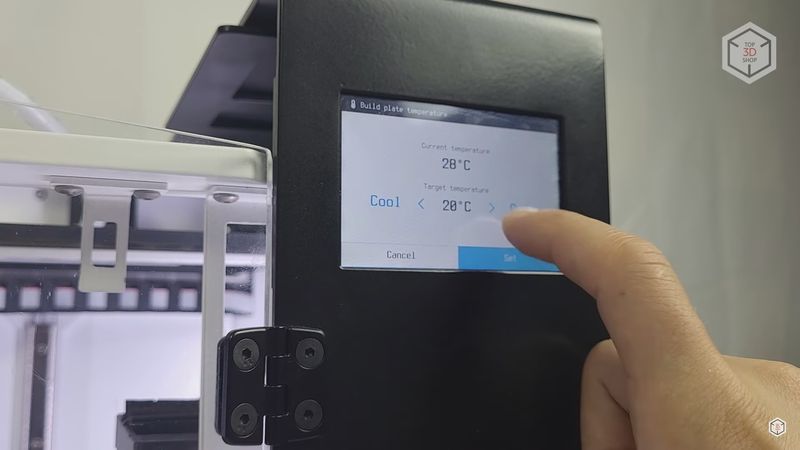
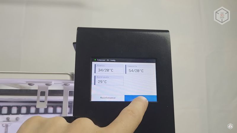
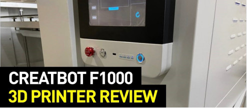
In the right top corner of the front panel, there is a touchscreen used to operate the printer, with a quality sensor and the menu interface reflecting the printer’s distinctions. The main screen shows the temperature of the two hotends and the heated print bed.
By choosing the corresponding option you get to the heating menu. Here you can manually set the desired temperature, there is also a button to turn the heating off and the Auto button. By tapping it you set the last temperature used. Both hotends can heat up to 270 °C; the maximum print bed temperature, as mentioned, is 120 °C.
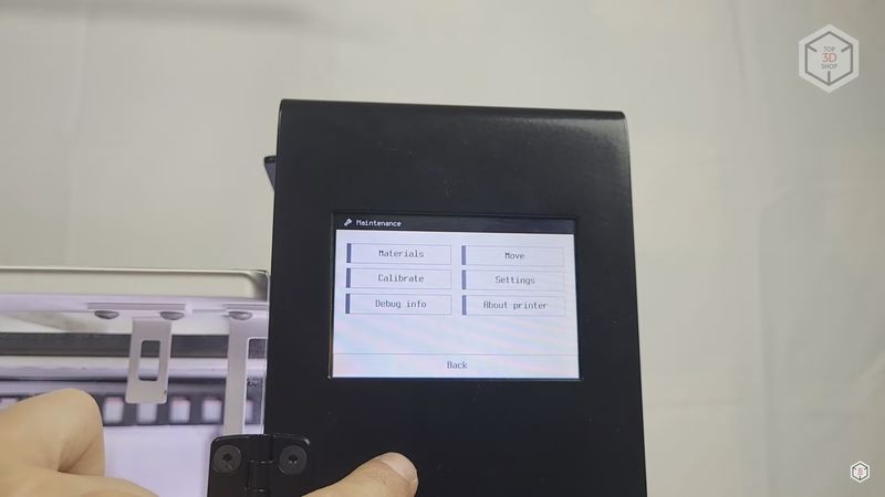
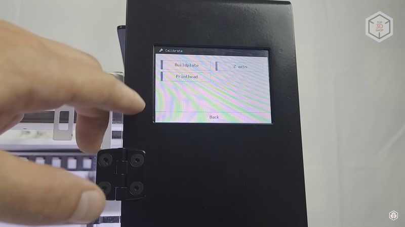
The Maintenance menu contains all the other functions and settings. The Materials option is an assistant for loading and unloading all materials. The Move menu allows you to manually move the axes of the printer. With the Extruders option in the Move menu you can control plastic and fiber feeding, as well as manually start the extruder change mechanism, cut the fiber, and turn on the print area blowing. The Calibrate menu contains the print bed and hotends calibration assistants. In the Settings menu you can manually adjust the offset of the hotends from the print bed and each other, these parameters can be adjusted during the calibration process. There are also Steps per mm and PID settings, but these are factory-configured, and you don’t usually need to change them. The Debug Info menu contains data on the axes and heaters status. In About Printer, you can find information about the printer version, firmware, etc.
And last but not least is the Print option, which allows you to send G-code files for printing.
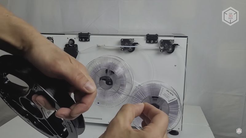
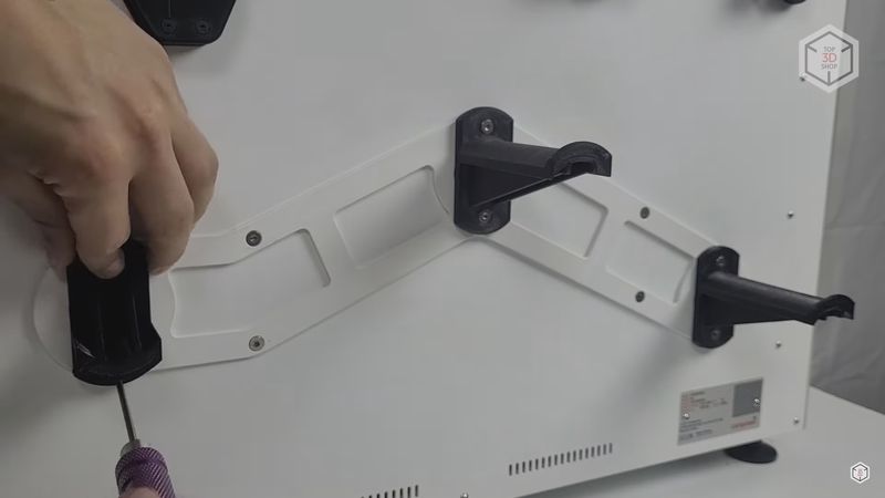
The printer comes fully assembled, the only thing you need to do is to screw the filament and fiber spool holders to the back wall. When you look at the back panel of the printer, the filament spool holder for the left extruder should be in the center. On the right is the auxiliary filament holder for the composite extruder. The short holder for the fiber spool should be mounted on the left.
The next step is to calibrate the print bed and the extruders. The printer menu offers the corresponding assistants. First, go to the Calibrate–Buildplate menu.
The printer will prompt you to heat the bed to the temperature required for printing. When it is done, the print head will pull back to the rear center point, where one of the three adjusting screws is located, and go down to a height of about 10 mm. Via the printer menu, gradually raise the print bed, reducing this distance.
Put an A4 sheet of paper between the nozzle and the print surface and wait until you feel the light resistance of the paper sheet when it is moved, just as it is done with any other printer.
Press Next on the screen — and the print head will move to the near left corner. Adjust it with the help of a paper sheet by simply turning the screw. Once again, press Next and adjust the right corner in the same manner. Then you need to repeat the entire process to make sure the bed did not tilt during the first adjustment.
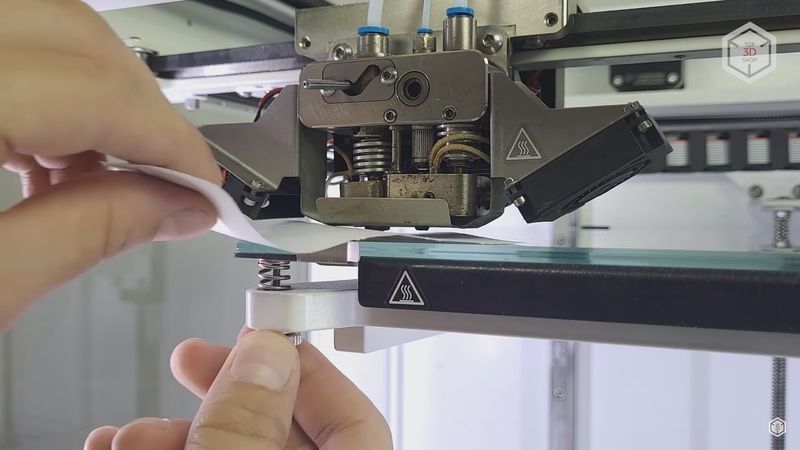
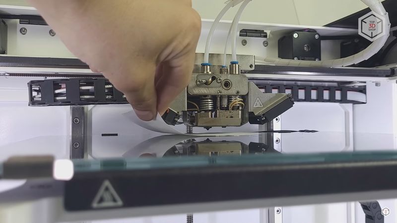
Next, it is necessary to check the left extruder offset on the Z-axis. Go to the Calibrate–Z-axis menu. The printhead will move to the center of the print bed and stop at the height of 10 mm, just like with the first calibration. There is nothing new here, just put a sheet of paper and move the print bed up via the printer menu until the paper can be moved with a slight resistance.
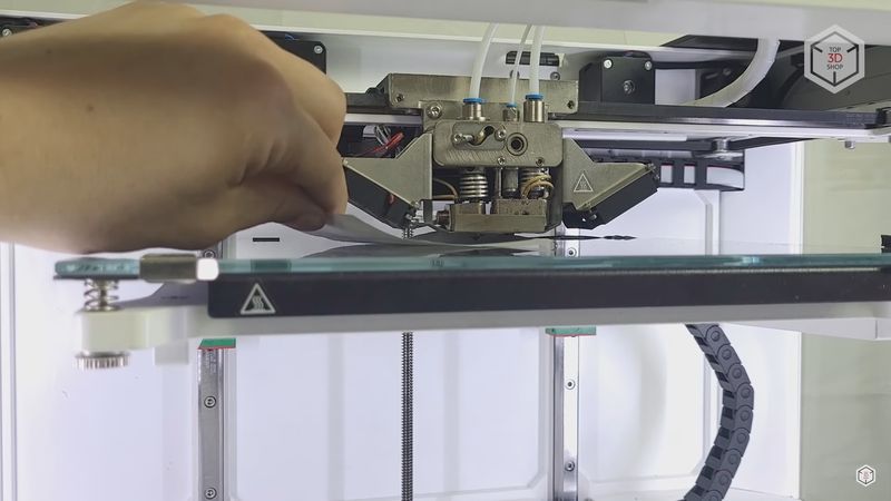
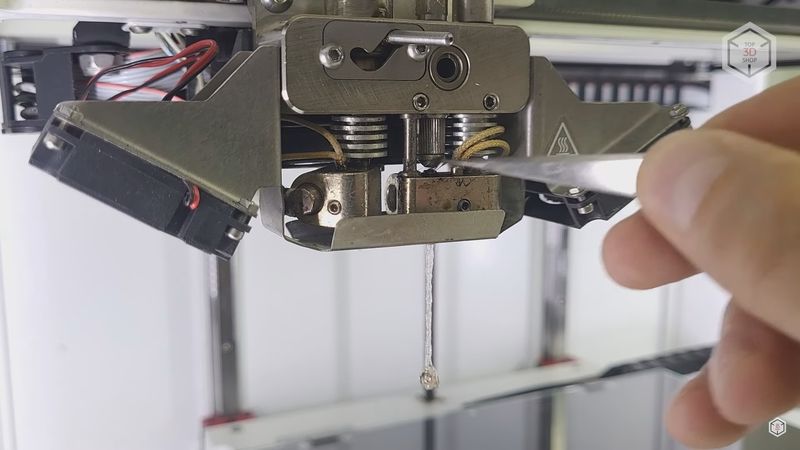
The next, and probably one of the most important steps, is to calibrate the offset of the composite extruder from the plastic one on the Z-axis. Go to the Composite Z-offset calibration menu. The print head will move to the side and elevate the left hotend. After that it will go to the center. As in the previous step, adjust the height of the right extruder with a sheet of paper. In this case, the sheet should pass between the nozzle and the print bed almost freely, with the right distance being about 0.3 mm.
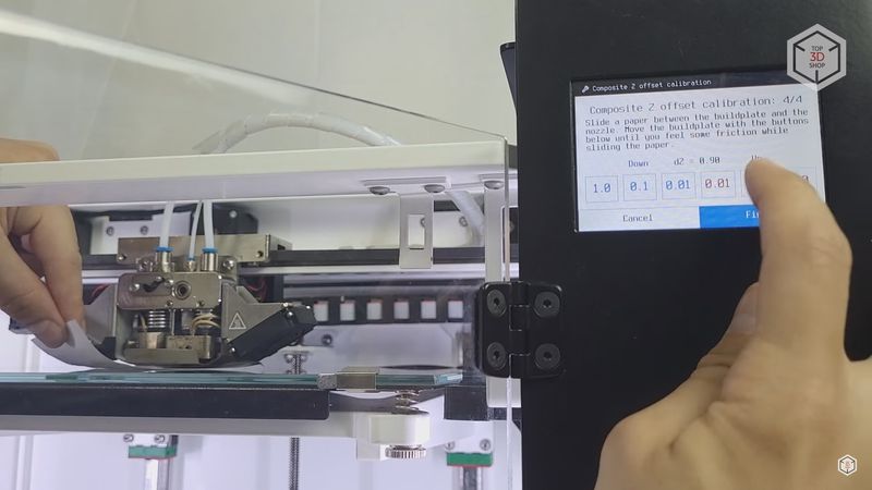
At this point, it is difficult to know if the composite hotend is leveled properly, and it requires certain skill. If the hotend is too high, the fiber will not adhere well. If it is too low, the fiber can break and clog the composite hotend when extruded into the plastic. And that is not the experience we would wish anyone to gain: cleaning the composite hotend is rather troublesome.
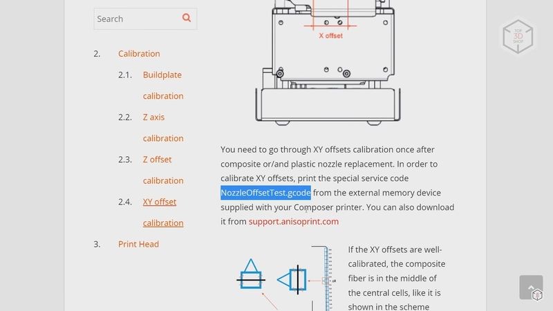
The last thing to do is to calibrate the XY offset of the hotends. For this, you need to print a test G-code file, which can be downloaded from the Anisoprint website. Be sure to load the printing materials beforehand.
If the printer is new, you can start loading immediately after the calibration. But if it’s been in use for some time, it is highly recommended that the composite hotend be thoroughly cleaned.
To do this, via the printer menu, turn on the composite extruder heating to the temperature you used last time. Now you can clean the hole all the way through from the nozzle to the hotend with a small drill or a special needle. While cleaning you will see plastic remnants on top, you need to carefully remove them with fine tweezers. Continue until you are sure that the channel for the fiber flow is clean and has no residue on the walls.
After that, you can start loading materials. As with the calibration process, there is a special assistant in the printer menu to help you do this. For the left hotend, everything is simple. Its spool should be located on the central holder, and the left hotend feeder is in the middle.
Insert the tip of the filament into the feeder. Go to the Materials – Plastic – Load menu. Heat the hotend to the desired temperature and then follow the instructions on the screen. At first, the filament will move fast, slowing down when approaching the hotend. Wait until the plastic starts to come out of the nozzle, and then you can finish the loading process.
With the composite hotend auxiliary plastic, the procedure is pretty much the same. The only thing to take extra care of is the droplets of plastic that appear when the filament starts to come out of the nozzle, at the same moment slightly squeezing over the heating block from the fiber inlet. These droplets must be carefully removed with tweezers so they won’t interfere with the fiber feeding.
With fiber loading the procedure is still the same. Just remember that the fiber must be handled with extreme care. First, never let go of the loose end of the fiber, otherwise the spool will unwind immediately. In this case, you will have to unwind it to the point where the fiber is straight, and gently wind it back on. Secondly, take care when touching it — if you lead your fingers over the fiber, it can leave splinters under the skin. Be sure to wear protective gloves or at least do not press your fingers against the fiber.
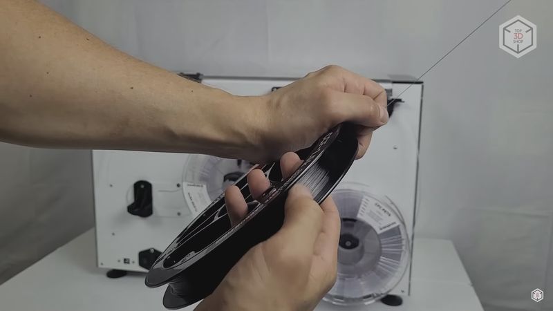
Place the fiber spool on the short holder, gently bring the tip to the feeder, and slightly twist the feed gear of the motor until the feeder grips the fiber; then follow the instructions on the screen. The fiber will begin to move forward and emerge from the right hotend. When the loading process is finished, the knife will cut the fiber, which is to be manually removed from the hotend.
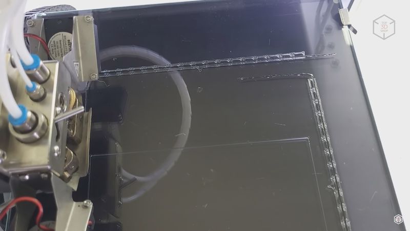
When the materials are loaded, run the file downloaded from the website to calibrate the extruders’ offsets. The device will print a large rectangle for you to see if the Z offset calibration has been done properly. It will also print two rows of small rectangles for the X and Y axes. After that, the hotend will switch over, and the printer will build one line with the fiber on top of these rows.
You need to find the small rectangles where the fiber runs exactly in the middle. Then define the position of these rectangles relative to the center and thus calculate the necessary offset. The row of rectangles that goes from left to right is responsible for the Y-axis offset. Each of the rectangles corresponds to an offset of 0.1 mm. To the right of the center there are positive values, and to the left are negative. The row that is printed front to back is responsible for the X-axis. The positive values are to the front, the negative ones being to the back. Once you have calculated the required offsets, you need to make the appropriate adjustments in the printer settings.
All of these procedures are described in detail in the instructions on the manufacturer’s website. If something is not clear, you can always find the necessary information there.
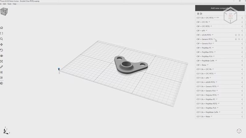
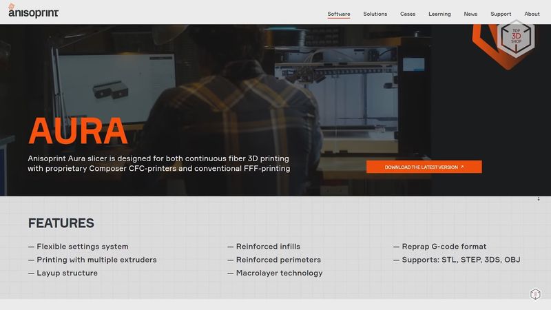
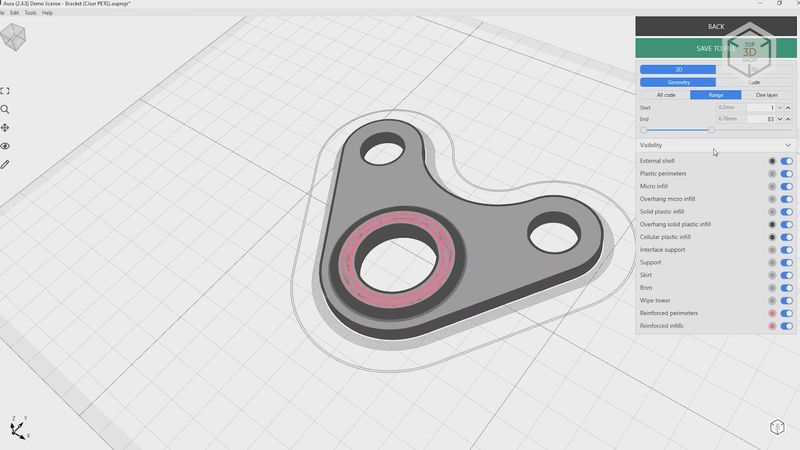
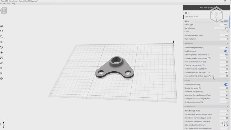
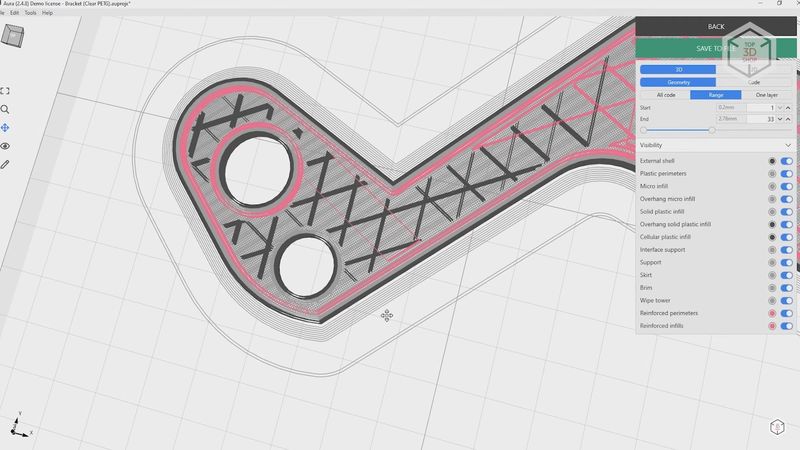
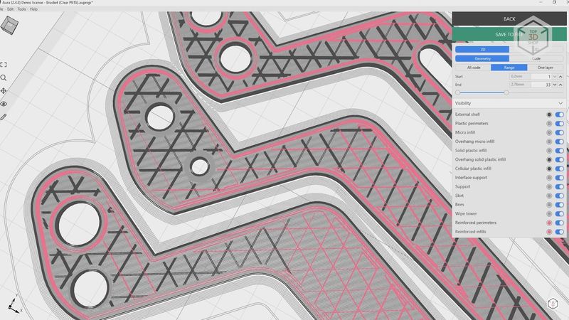
To prepare models for printing, Anisoprint offers a proprietary slicer called Aura. It allows you to slice models both for conventional polymer printing and for making fiber reinforced composite parts. Aura has three license types, differing from each other in the number of settings and, accordingly, in price.
The simplest license version called Neat provides access to the minimum set of necessary parameters. It allows printing with only two basic filament types, namely PETG, which is produced for Anisoprint by the REC company, and Smooth PA, a special polyamide produced by Polymaker. The Settings menu offers a choice only between these materials in conjunction with two fiber types. CCF is carbon fiber, while CBF uses basalt. It is possible to turn the reinforcement on and off for outer contours and inner holes with a line number adjustment, select and configure the reinforced infill, turn on the supports, and manage a few more settings. There is no way to change temperatures, speeds, layer heights, and the like. The slicing software will decide everything for you. This type of license is usually used by manufacturing companies. It gives you minimum settings, a limited number of supported materials, but at the same time more predictable and consistent results.
In comparison, the advanced Ext license gives you access to more material types, for which you can change temperatures and retraction parameters for the plastic extruder. For the composite extruder, there is only the choice from a larger number of materials. There is also an opportunity to adjust print profiles, but there are not a lot of options here. You can also adjust the type and percentage of infill for the plastic hotend, with a few settings for support structures and several more parameters.
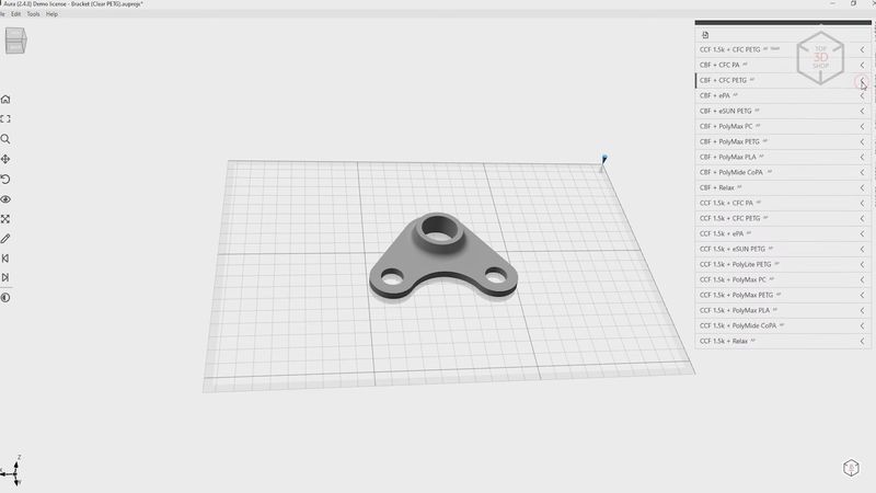
Finally, the most advanced license called Open allows you to adjust everything down to the finest parameters. This license can be helpful, for example, for research institutions. It opens wide opportunities for experimenting with the printer and various materials.
The Ext and Open license types are the second major difference between Anisoprint and Markforged. The latter offers a decent slicer, but it does not allow customizing any material or extruder parameters.
On the contrary, Aura enables you to adjust almost any parameters that might be of some help when using specific materials, like, for instance, chemical-resistant or easy-to-post-process materials. In addition, the printer firmware understands the common G-code commands, so if you have the appropriate skills and knowledge, you can operate the printer the way you’d like to.
We are not going to talk in detail about all the features of the Aura slicer, otherwise this would take long hours. In short, it offers an enormous number of parameters. We would like to mention only a couple of interesting things.
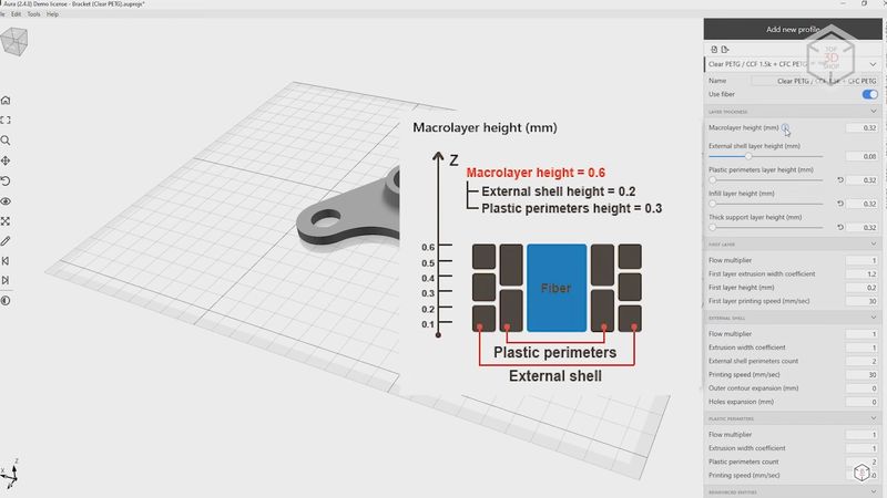
First, Aura uses the so-called macro-layer system. Its essence is as follows: different parts of the model, inner and outer perimeters, infills and supports can be printed with different layer heights, as if catching up with each other during printing. For example, inner perimeters can be built with a layer height of 0.3 mm to reduce printing time, and for outer perimeters the layer height can be set at 0.2 mm to give a smoother surface. Thus, a single 0.6 mm macro layer can contain two 0.3 mm layers of inner perimeters and three 0.2 mm layers of outer perimeters. Meanwhile, the height of the fiber-reinforced layers always corresponds to the height of the macro layer. This sounds a bit complicated, but you don’t usually have to adjust these parameters; besides, you can only access them with the Open license.
The second thing is the fiber printing speed, which is as low as about 10 mm/s, because of the specifics of the technology. And it is even slower at the beginning and at the end of the movement, because otherwise the fiber can have poor adhesion with the underneath layer, or even break. When printing with the plastic extruder, the speed is higher, but it does not exceed 50 mm/s in pre-set profiles. Higher speeds are possible, as the printer’s kinematics allow for it. Still, in order to avoid possible problems and print failures, they are not recommended.
One more thing we would like to mention is that the structure of the composite hotend does not allow building short sections of fiber. The minimum length here is 45 millimeters. After the knife cuts the fiber, it needs to completely come out of the hotend, passing a certain distance. Consequently, when printing small parts or narrow sections, Aura simply will not route for the composite hotend. For the same reason, there is no way to reinforce perimeters around small holes. The minimum diameter of the holes can be about 12 mm, depending on the number of plastic and reinforced perimeters.
These points must be considered when modeling parts you are going to print with fiber.
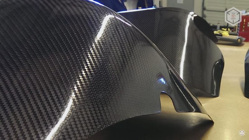
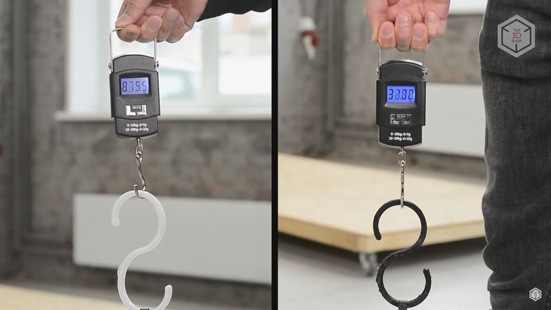
Finally, let’s move on to testing. We are not going to conduct any experiments to test the strength of reinforced parts. Full-fledged objective tests require special machines and typical parts. Without such equipment, simple attempts to break something give little information. Besides, we already did an experiment with scales once. Then it took about three times as much force to break a small hook reinforced with two fiber contours as it took to break an ordinary plastic one made of PETG.
As for some objective values and figures obtained under laboratory conditions, you can always check them on the Anisoprint website.
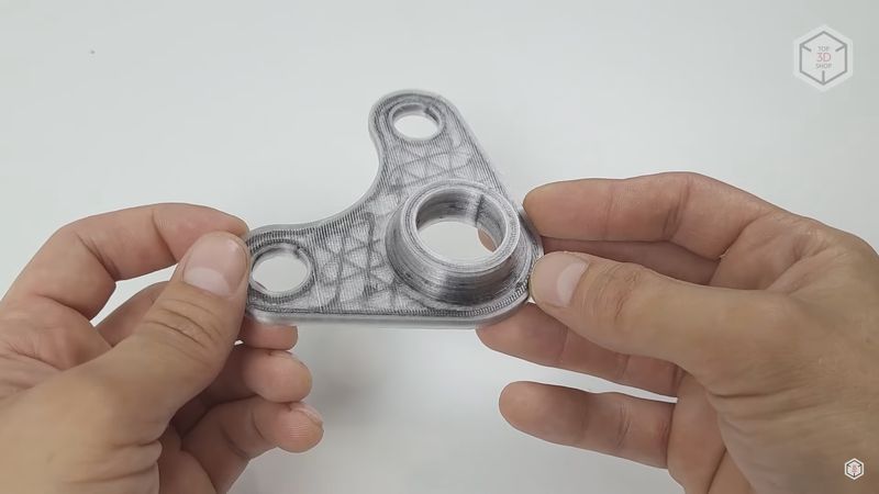
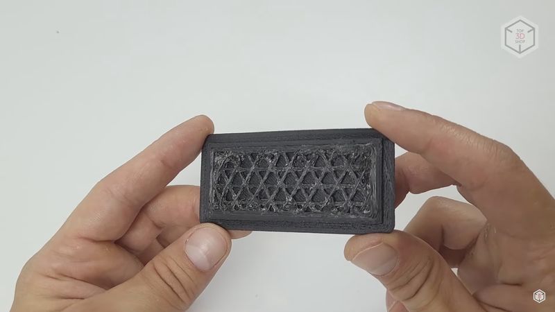
So, we took PETG filament along with carbon fiber and tried to print one of the examples that the slicer offers at the start. This is a small part with three holes. No major problems were encountered during the process.
There were some moments when the fiber would slightly bend next to the nozzle at the beginning of a new layer. We may have done something wrong while calibrating the composite extruder. It did not look very nice, but gradually these areas were covered by the upper layers and smoothed out. And the top plastic layers ultimately hid these flaws.
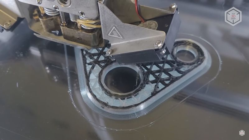
Besides, when printing the reinforced contours, fiber particles sometimes got on the plastic perimeters, leaving small black dots on the surface. We do not have any complaints about the plastic extruder, as it did everything right, though not fast. Overall, the part turned out pretty good. Might be not as neat as shown on the website and in the brochures, but for the first test it was okay.
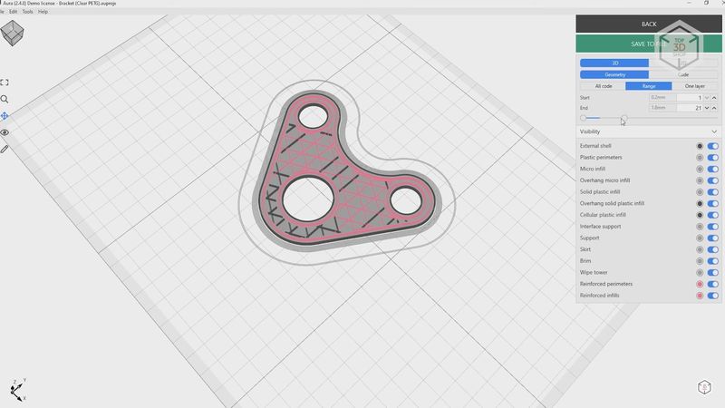
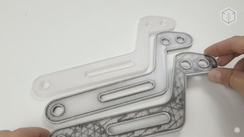
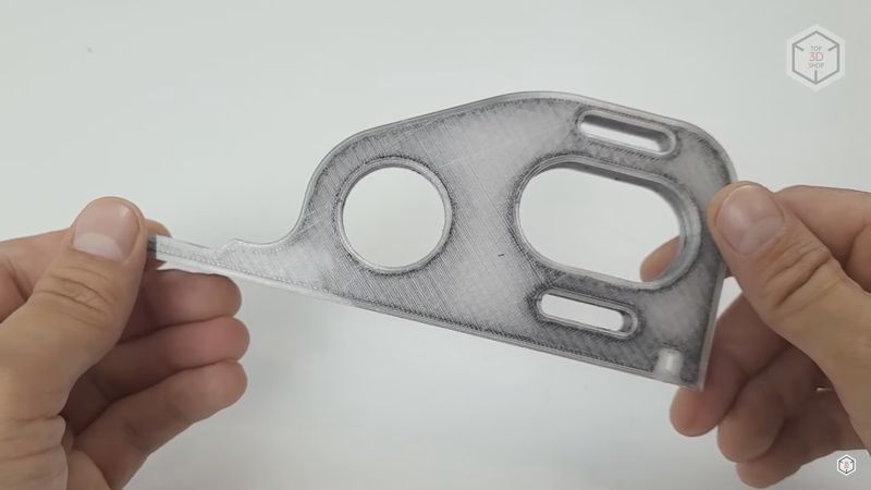
For the second test, we modeled a non-complex part to print it in three ways. It is a kind of a lever with holes and a notch. In the first version, we printed it with PETG only, and in the second version, we added reinforced contours. For the third time, we used both reinforced contours and reinforced infill.
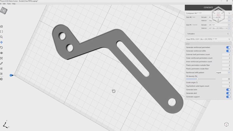
As expected, the plastic part turned out to be the softest and the most unstable. The sample with reinforced contours felt much stronger, not only along the fibers, but also across. Apparently, the fiber fused into the plastic gives the reinforcement effect and strengthens the part in all directions. And the part with the fiber added wherever possible felt the most rigid. The quality of the printed parts is very good, although the same difficulties as in the first test also occurred. They were especially evident on the fully reinforced part.
In addition, at the modeling stage we encountered constraints related to the minimum distance of fiber printing. For this reason, the holes in the part are as small as possible for Aura to design reinforced contours around them. And in the narrow areas near the notch, the reinforced infill turned out to be incomplete. In the most important areas, though, everything was printed as it should be. But this had to be taken into account when modeling.
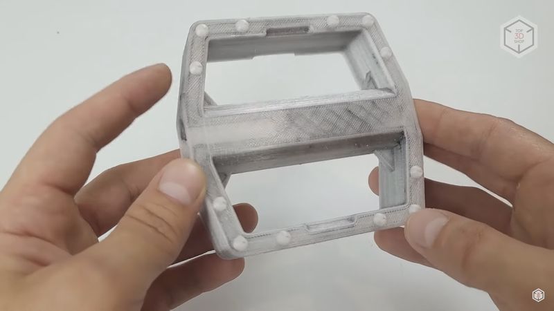
For our third and fourth tests, we tried printing parts not designed for this printer. The suspension element of the radio-controlled car turned out right only with reinforced contours. The fiber infill was almost nowhere to be found. And even a couple of areas that could be good to reinforce came out purely plastic because of the specifics of the model. In other respects the part was printed well, being definitely stronger than the non-reinforced part would have been.
Another thing we printed in the course of testing was a bicycle pedal. It allowed us to combine both the reinforced contours and the infill. Again, though, there were some areas with none of it. With this model we checked the Aura slicer’s ability to build support structures, and they were built well and easily removed without leaving any marks on the surface.
For the next test we decided to check how the printer would manage simple printing with randomly chosen old cheap ABS plastic without any reinforcements. We printed some housing parts for the power supply unit.
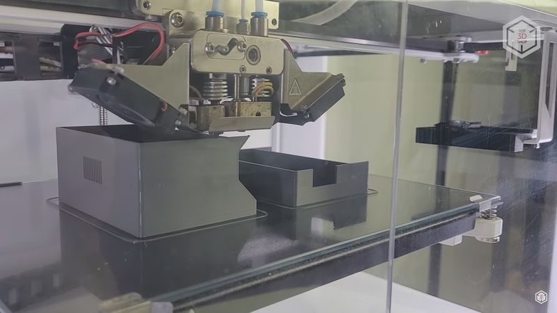
Everything went well: thanks to the passively heated build chamber, no shrinkage of the ABS occurred during the process. The corners did not peel off, the thin walls did not crack. After the cooling, the parts remained flat. The only weak point was the visible layering in the grid areas — apparently the minimum retraction distance in the slicer was set too large for such gaps. And the transfers in these areas took place simply without retractions.
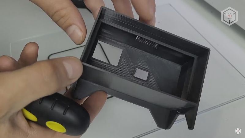
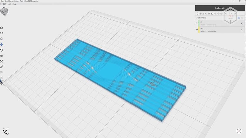
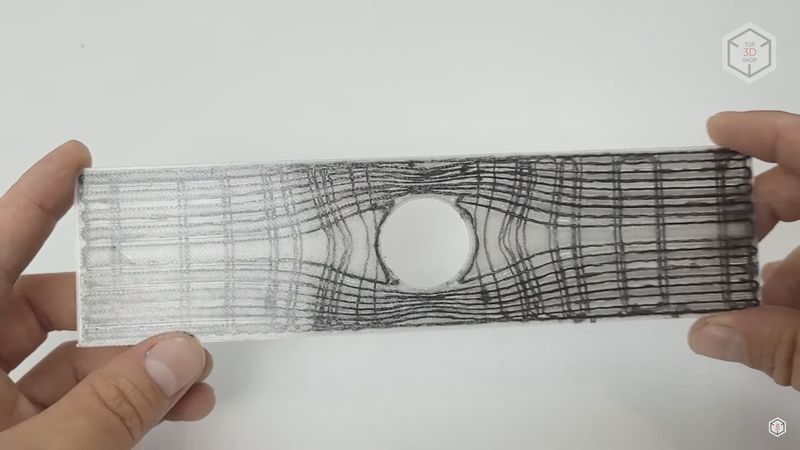
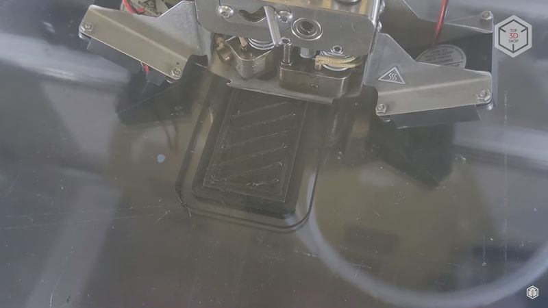
Next, we tried to print another model offered by the slicer. The model is quite interesting because the fibers here are laid along certain calculated routes. Such parts have to be prepared separately. Roughly speaking, these are three models combined in one STEP file. The first model is the base, it will be printed in plastic. And the other two are designated as so-called masks, and will be reinforced.
Thanks to correctly calculated loads, the part has almost the same tensile strength along its entire length, despite the weak area with the hole in the middle. When calculated properly, this printing method provides the best strength results, because you are not tied to automatic algorithms and can decide where and how the part will be reinforced, and where it is not necessary.
For our final test we decided to experiment with materials. In the majority of profiles Anisoprint suggests using the same material type for both extruders, and only for the plastic hotend the material can be filled. Still, we tried using pure polyamide with carbon fiber for the composite hotend, and loaded the plastic hotend with fiberglass-filled ABS. The printing temperature for both materials is about 250 degrees. But will the fiber with nylon be able to adhere properly to ABS?
First we printed a small test rectangle — and it turned out that such a combination worked quite well. The reinforced infill and contours laid on the ABS without any problems.
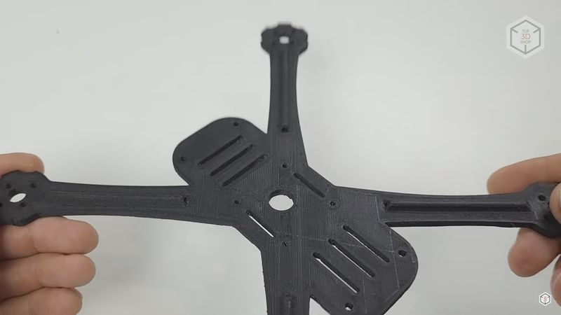
So, we tried printing a small frame for a racing quadcopter in the same manner. All went good — the frame was printed out, the fiber laid well, and the covers closed. The experiment can be considered a success.
The only thing to keep in mind is that for such experiments with materials you need Aura with the Open or at least Ext license.
Overall, the Anisoprint Composer A4 is an impressive device. It employs an original technology which allows you to print light-weight and strong parts with complex geometries. Even in spite of the low printing speed, the production of such parts will be faster and easier than with other methods. It is possible to use materials with different properties, such as abrasion- or chemical-resistant. The print quality is totally decent as well.
With that being said, the printer requires a certain amount of skill. A single mistake in calibration may lead to a couple of hours spent on cleaning the composite hotend. Once we had such an experience. The construction of the composite hotend and the specifics of fiber placement require a good understanding of the process and proper model preparation for this printing method.
If you need to print very strong lightweight parts reinforced with basalt- or carbon fiber, if you are not afraid of the difficulties that can arise during operation, and you want to have access to all the features of the device and all the settings, then you will not find any analogs to this printer.

Update your browser to view this website correctly. Update my browser now
Write a comment