Hello! Today you will find out about the advantages and subtleties of working with composite materials, including those in 3D printing.
Why does ordinary carbon fiber reinforced plastic not give carbon properties to a printed product? How should the fibers be arranged in material for the highest print strength? What is the novelty of Anisoprint's approach to printing with composites and why is it worth paying attention to?
The material below is a lecture by Fyodor Antonov, CEO at the Anisoprint company. This speech was presented at Top 3D Expo.
Hello! My name is Fyodor, I really like to talk about composites and I'm going to tell you why they are used, what is their advantage. Besides, I’ll tell you a bit about how it relates to 3D printing and what you can get by combining it with the given field.
3D printing is known to be an additive technology. Composite manufacture technologies, which appeared long before the emergence of 3D printing, were also additive from the very beginning. These technologies are quite numerous. But what we are doing now is a novelty both for the production of composites and for 3D printing, that is, for the additive field in general.
I will start with a short story about composites and carbon fiber reinforced plastic in particular (colloquially referred to as carbon), which is also called the king of composites. What are its advantages over metals? For example, take some kind of aviation aluminum alloy and look at its characteristics.
It has density, we are also interested in, for instance, temporary resistance and strength.
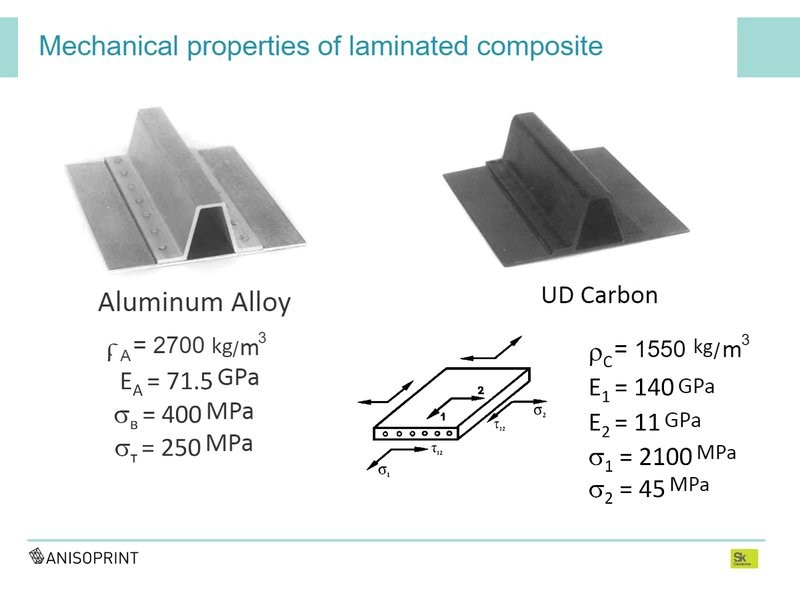
There is unidirectional carbon fiber that is almost two times lighter and five times stronger than aluminum. Thus, the specific strength of unidirectional carbon fiber turns out to be 10 times higher, compared to aluminum.
If we compare it with some steel, even the hardest one, the difference will be still greater — because steel is very heavy. That's why a great many people opted for carbon fiber and began to use this unique material for making highly loaded essential structures — first in rockets, then in airplanes; now in cars and a number of consumer goods.
Carbon fiber is a composite, one of the main features of which is that all these unique properties and all of its strength are along the direction of reinforcement, along the fibers. In the transverse directions, its properties are two orders of magnitude lower.
How engineers “fixed” carbon
For some reason, people decided that the vector of carbon fiber was a big drawback and started to think how to get rid of that. They began to place layers of unidirectional carbon fiber on each other at different angles to get the so-called quasi-isotropic laminate, which engineers working in this field like to call "black aluminum."
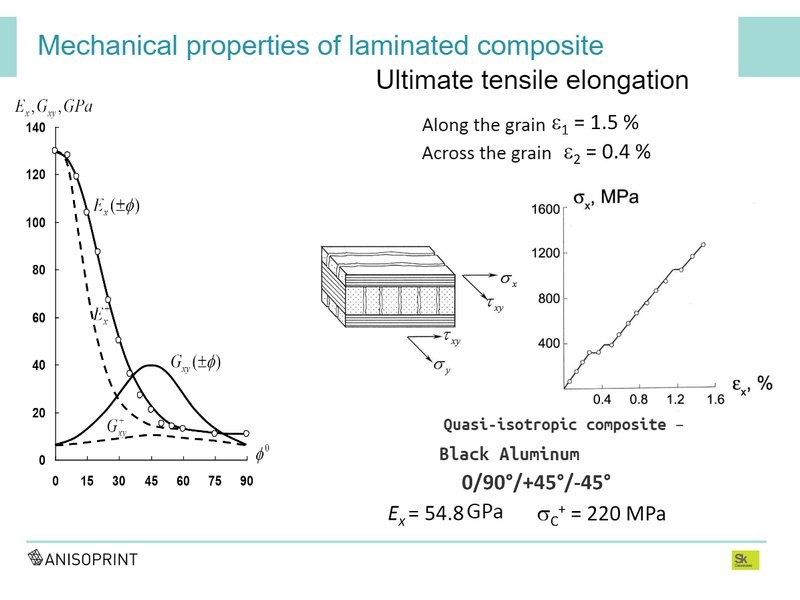
As the name suggests, its properties resemble those of sheet aluminum; it is used in approximately the same structures: an aircraft fuselage, wing, a rocket body. After the properties of carbon fiber were “smeared out" in different directions, its strength became about 10 times less. That is, it came close to ordinary aluminum.
So, we lost all the wonderful advantages that unidirectional carbon fiber had, at the same time we got a lot of problems associated with the technology, impact resistance, fracture features, with the connections of such nodes to each other. There was a whole range of complex problems, in fact. Therefore, in the latest generation of civilian aircraft, there were 50–60 percent of composites, and in the next generation, as industry experts say, there will be at least only half of them. That's why the Dreamliner program was a total failure for Boeing. All the hopes that aviation pinned on composites have not been realized precisely because of the attempts to make carbon fiber “omnidirectional”.
Still, there is another approach, which is different from “black aluminum”. It is very effective to make from composites the so-called mesh constructions, such as the Shukhov Tower. Here, at the top, shown is the payload adapter of the Proton-M launch vehicle, which is made of carbon fiber — not of “black aluminum”, but in the form of a mesh structure with fins of a certain direction and a certain density. The part weighs about 50 kilograms and can withstand a load of 200 tons. A similar part for the same needs made of a carbon fiber sandwich weighs 30 percent more and can withstand less load. With aluminum it’s even worse.
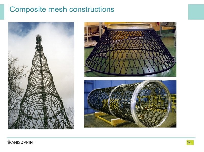
In this design, the composite only works along the fibers. It can't work transversely, so all of its anisotropic properties are used as they should.
In addition to mesh structures, there is another interesting direction called “Fiber steering”. The idea is, fibers are placed not at fixed angles in a straight line but along curved paths so that the directions of the fibers at each point correspond to the directions of the main stress vectors in the part.
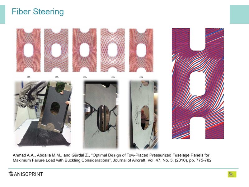
This is the aircraft fuselage panel with an inspection hole. It was made by means of automated laying. Now some call it 3D printing as well, though this technology is several decades old, having been long and actively used for the manufacture of parts from composites, along such curved paths.
Comparative tests of such parts and “black aluminum” were carried out. This styrene-based fiber panel, with the same weight and nature of the load, can withstand 30 percent more compression load. The nature of the destruction is also completely different. Such a panel works much more efficiently.
One of our main ideas was to enable structural engineers to fabricate, produce and design really effective structures from composites; to move away from “black aluminum” and make the anisotropy become the main advantage of the material — not its deficiency, as many believed. That is, we say that isotopic material is good, because, knowing how the part works, knowing the loading conditions and cases, knowing the internal forces and stress, we can focus the properties of the material at each point, in the very direction in which it is needed. Thus, we get a whole additional space for optimization. We can optimize not only the shape of the parts but also their internal structure.
Unfortunately, traditional automated technologies for manufacturing parts from composites don't allow fibers to be placed arbitrarily at every point. When we first started to deal with this subject, which has grown into the product that we are presenting at this exhibition today, it grew from the idea that we want to make composites in which you can arbitrarily control the direction of anisotropy and its degree in every point of the material. Old technologies did not allow this. Then we decided to look for something that could bring us closer to this goal. And 3D printing technologies turned out to be very useful here.
What is actually done with composites in the world of 3D printing? The commonest thing: when we say that we print with carbon fiber, we are told that everyone prints with carbon fiber. No, everyone doesn’t print with this kind of carbon fiber. Usually it is plastic filled with chopped fibers; in fact, ordinary plastic with a filler, isotropic material in which we don't control these fibers in any direction.
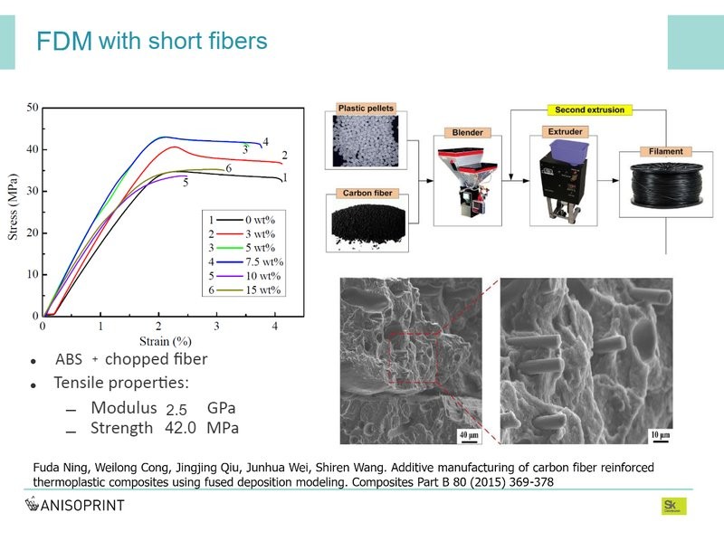
This, to be sure, is also an interesting thing, but there are absolutely no properties close to those of real composites here. The material is a little harder (well, two or three times) than ordinary plastic. Sometimes it can be a little stronger. It behaves much better in shrinkage. These technologies, for example, are successfully used for printing large-sized parts — say, of several meters. But from the point of view of design and technology in general, this approach gives nothing new. This is ordinary FDM, or, as in this case, SLS, when we add finely chopped fiber to the polyamide powder.
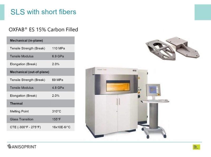
Speaking about the properties, yes — at OXFAB, it is an SLS-machine for printing composites; the print strength declared in the plane is 110 megapascals, and for ordinary not filled polyamide it's around 40–50. This is better than ordinary plastic, but not very much.
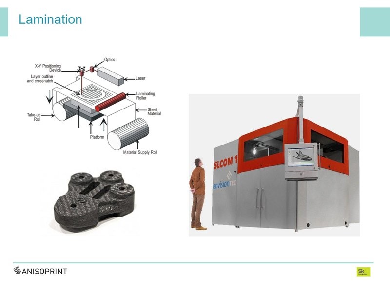
Apart from chopped fibers, there is an interesting option with fibers long — for example, lamination technologies. I know three or four, I guess, but here I’ll talk about one of them. Honestly, I don’t know what the fate of this project is. A couple of years ago, EnvisionTEC seemed to show it as a prototype on FormNext. This is not an entirely additive technology.
They use sheets of carbon fabric pre-soaked with thermoplastic, the so-called “prepregs”. In one area, this sheet is cut out along the contour of the layer, possibly by ultrasound; in another area, it is rolled and laminated, thus forming a layer. This is pure "black aluminum", only made with the help of a special machine. So, it is quasi-isotropic material in which there are all the disadvantages of “black aluminum”, such as the rupture of the fibers and, as a consequence, stress concentration and edge effects which lead to holes and joints becoming very weak spots.
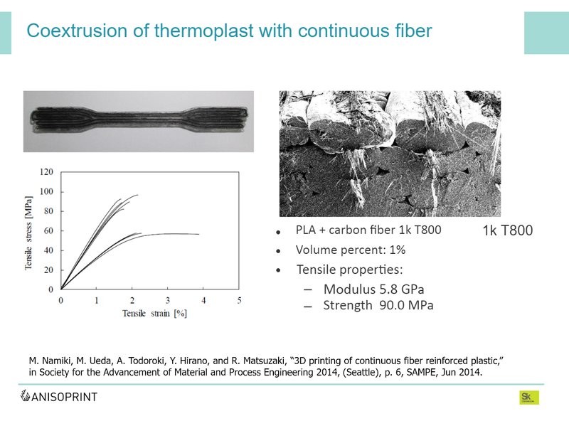
The next step, a little closer to what we started to do, is the extrusion of thermoplastic with continuous fiber. In fact, this is the FDM technology, but reinforcing fiber is continuously added to the nozzle during the printing process. Quite a few scientific groups around the world are engaged in such things.
The problem here is that structural fibers are not monofilament, they consist of hundreds or thousands of micron threads, and if we just add this fiber to the melt of viscous plastic, it doesn't get inside and impregnate the fiber, so the composite doesn't form. Inside appears one big pore. There is no composite, because the composition must have reinforcing fiber and binder that connects all the components, making them work together. In this case, it doesn't happen. Therefore, though the tensile strength can be quite large, there are no special characteristics for compression in such materials. If you look at the microscopy, inside are a lot of pores between the fibers.
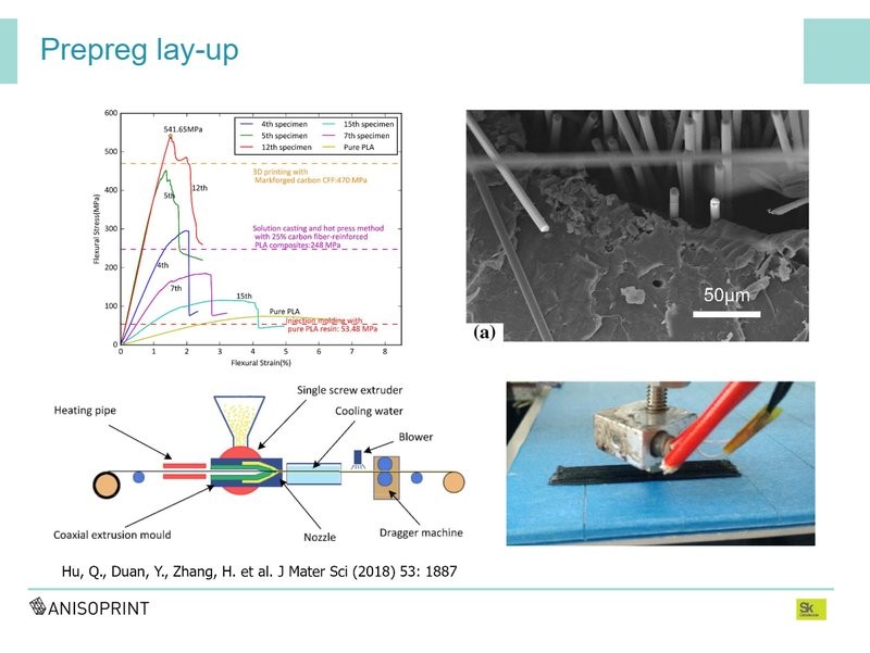
The second approach is a little more successful, I call it “prepreg laying”. We take the same fiber, for example, carbon or glass, and in advance, with a special machine, impregnate it with viscous plastic under high pressure, or soak it in solution and then steam, and stretch through a die.
That is, we are trying in advance, with a special machine, to place this viscous plastic into the fiber. As a result, we get an impregnated filament, which is traditionally called “prepregs” in the composite industry. In other words, a semi-finished product for the manufacture of a composite. Then we heat this “prepreg” through the nozzle and form a part by means of extrusion or laying.
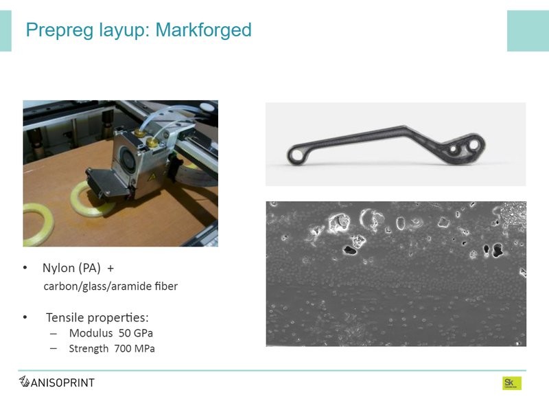
The most famous example of 3D printing using continuous fiber seems to be the American company Markforged. They've been selling these systems for quite long. It is a prepreg laying as well. They, too, use carbon fiber pre-impregnated with nylon and a nozzle in which it is heated and laid out. Besides, there is an additional plastic nozzle for printing with plastic alone. Markforged prints have pretty good specifications. Durability is over 700 megapascals. There is a choice of reinforcing fiber types. Yet, the number of pores is very large, which is also evidenced by many articles where the microstructure of these materials is studied. The reason for that is either because the impregnation is poor or it is nylon, which draws water and boils during printing.
We impregnate the fiber beforehand — not with thermoplastic but with thermoset, which provides better, cheaper, and more reliable impregnation of this fiber. We call this process co-extrusion. Since such a fiber cannot be melted, we separately add plastic during the printing process. The result is a two-matrix composite, in which inside the fiber we have non-meltable thermoset, which provides impregnation of the fiber, and between the fibers we have thermoplastic that binds them together.
In our case, this plastic can vary. If you need non-combustible plastic, or colored, or plastic with resistance to certain chemical or temperature impacts or the environment, you can choose the one that suits you, because all the basic surface properties of the material are determined exactly by the binder — the matrix. Due to the fact that fiber and plastic are provided separately, we can locally change the volume fraction of fiber and plastic in each point. We can use less plastic — then we have a larger volume fraction of fiber — or we can use more, so it decreases. Thus, we can control the degree of anisotropy and, more importantly, print mesh designs with fiber intersections within the same layer. We can lay reinforcing fibers on each other, at any angles we need, within every layer individually. At the same time, the thickness of a layer doesn't increase at the intersection, changed is only the volume fraction of fibers in this very place.
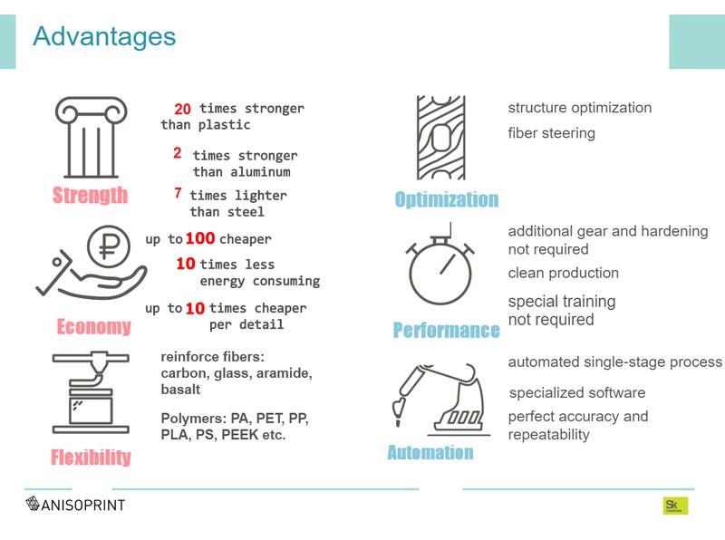
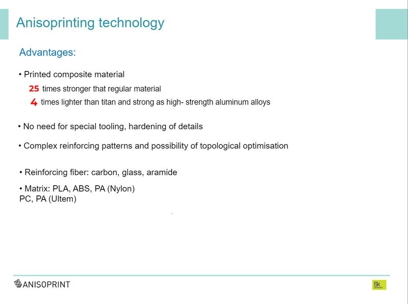
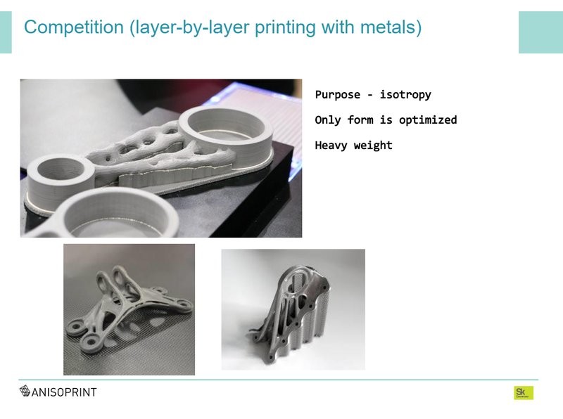
There are a lot of advantages. What a confident promotional slide. 20 times stronger than plastic, twice as strong as aluminum, much cheaper than printing with metal. Everything that I said about optimization, automation, clarity — all that is also typical for this technology, as well as, though, for some competitors' technologies.
Another advertising slide that I've been showing at all conferences for a long time. If we take the cost of equipment on the x-axis, on a logarithmic scale, and the the specific strength of the material on the y-axis, that is, the strength referred to the specific weight, then all the metals printed with SLM technology are at the bottom of the graph, with titanium being the best one.
We naturally have the whole technology patented.
For these printers, we created our own specialized software called Anisoprint Aura. It's a slicer, you can control the reinforcement, set the plastic perimeter and plastic filling, composite perimeters, composite filling, supports — basically the whole functionality of a conventional slicer, plus functionality for working with reinforcing fiber.
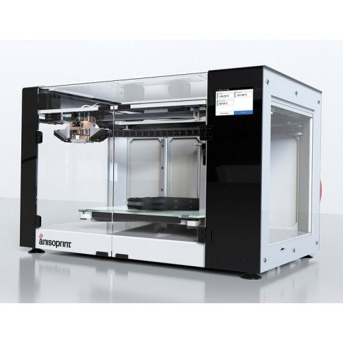
It has a closed casing and heating bed, the frame is made of milled aluminum plates with rail guides along the z axis. The design is CoreXY.
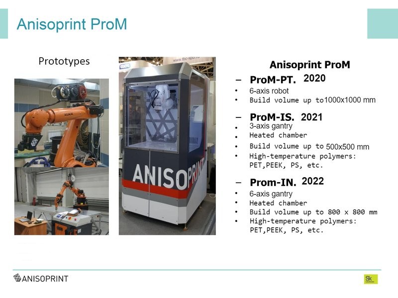
Our main goal is industrial equipment for 3D printing of composites. We have a number of prototypes successfully used by our partners. We already showed the prototype of our first industrial printer Anisoprint ProM-PT at a metalworking exhibition, which we'll once again show in working condition at FormNext. Sales are planned to take place from the second half of 2020. The novelty is that it has a six-axis industrial manipulator instead of a portal system, which allows of laying the fibers not only in the plane but at any angle.
So, on a regular flat scheme, I can print such details where I have reinforcement inside the plane. As soon as I need to leave the plane and, for example, reinforce in another direction, I've got to have more freedom, for which we are actually developing this six-coordinate machine. In addition to an industrial robot, there's also a whole set of industrial electronics — not step-changers but servos, a BOSCH controller which is integrated into the robot controller. All this provides reliability, repeatability and redundability, meeting the industry requirements.
Our next planned industrial product is a three-axis device for printing with high-temperature plastics such as PEEK and PSU.
Well, the very top appears to be an additive machine for the manufacture of high-temperature parts in six coordinates, but that is our long-term goal. The technology is intended for the production of parts of complex shape from composites optimized for a given load and a given working condition.
Basically, this type of parts made of composites is not produced. That is, if you want to make such a part from a composite, our method is the only one existing. Other technologies for manufacturing products from composites are mainly designed for large-sized sheet parts or sections and girders. With our technologies, it is possible to produce parts of complex shape. But we're also going to fight with metals to gain a market share. Such type of parts as brackets, connection elements, housings — all loaded parts of complex shape are made by means of milling or casting. They are far easier to make with our technology.
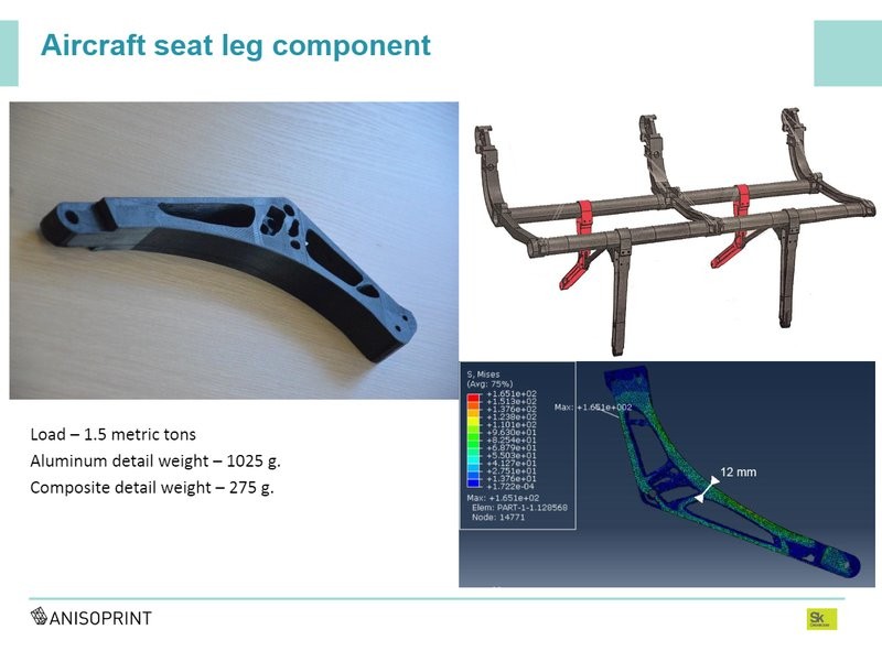
Well, since I'm holding this part in my hands — this is an element of a leg of an aircraft seat; the original aluminum part weighs 1 kilogram and is meant for a load of one and a half tons. Here it is: an optimized composite part made by us, designed for the same loads. It weighs 275 grams, almost four times lighter. The cost price of a part will also be lower than that of milled aluminum made with the help of a multi-axis milling machine.
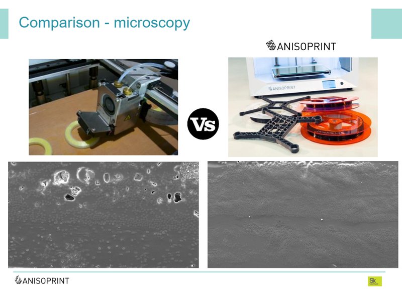
Another comparison illustrating the difference. It lies in the fact that we can provide reliable impregnation and the absence of pores in the material, which is extremely important for certification, for critical parts and essential structures. We call this technology “anisoprinting” — it’s not just 3D printing, these are different things.
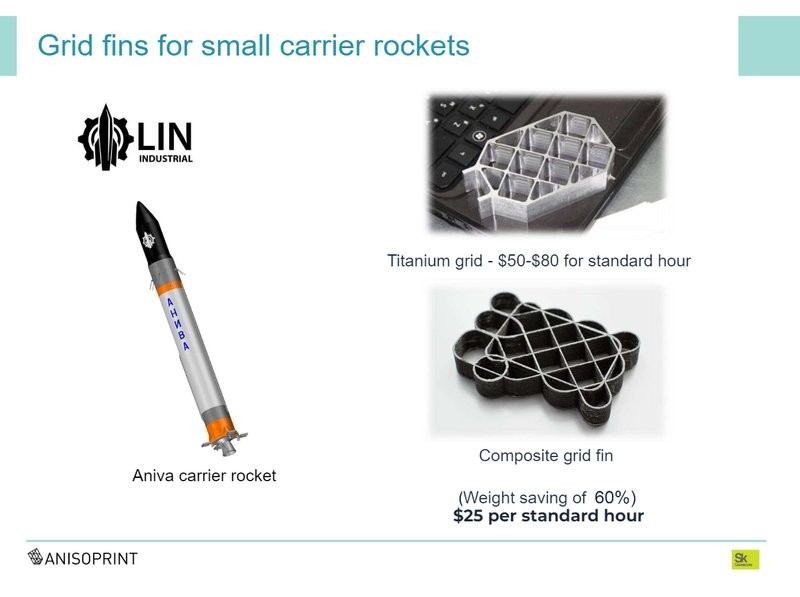
This is a rather important point: there is a fancy direction in the design of engineering products called topological optimization. I won't go into details. In most cases, parts resulting from this generative design have the form of mesh structures. Naturally, we have no questions about in which direction the fibers should be laid in a fin. A fin is a one-dimensional structure that works either for strain, or compression, or bending. It won't work on lateral separation, because the dimension is too small. It won't work on the interlayer shift either, only when bent. Thus, the properties in the transverse direction in the fin, the properties of the material across the fin are redundant. It makes no sense to make these fins from isotropic material, because the transverse properties are not needed there. They are not to be the same as they should be along the fin. That's why it is necessary to use isotropic materials. This is the best example proving the advantages of anisotropic materials over isotropic ones.
A few examples of what we did and a few words about a still more distant future as we see it.
This airplane in the corner is the Airbus concept called Airbus 2050. Here the artist or designer, probably not an engineer, depicted a mesh fuselage on the plane. I don't know what he invested in the picture, but what we want to learn is how to do this very type of product in the future. There are fins here — the best use of composites. Such a design will work most efficiently. In addition to its reinforcement being along arbitrary paths of anisotropy control, various functional fibers, functional elements, inserts and electronics can be added during the production of this type of parts. It's possible to produce adaptive materials, adding various "healing" agents. Something like this, in our opinion, should be the future of production in the long run. And, of course, the main material should be composites.
You can get a 3D printer for printing with Anisoprint composites or order an industrial model at Top 3D Shop.
Update your browser to view this website correctly. Update my browser now


Write a comment