
Autodesk Fusion 360 is a 3D modeling, design and calculation software that combines CAD, CAM and CAE tools in a single system.
This software can become a great asset both for hobbyists, in light of an individual licensing system, and for professionals, considering the attractive cost of licensing for commercial use. Fusion 360 has many advantages over other CAD software. Read on to learn more.
Fusion 360 is based on the Inventor, a user-friendly design and simulation program that also houses tools for creating models and assemblies. Then the company released an even more successful and modern piece of software — Fusion 360, which is mainly cloud-based and capable of enabling group access to projects and cloud storage. It was an innovative solution, and the process of creating the interface was mainly inspired by users feedback, while some of the options and add-ons were integrated after software engineers and active users joined efforts. One of the key features of Fusion 360 is combining all of the stages of creating 3D parts and designs, from a prototype to a finished product, in a single sustainable workflow.
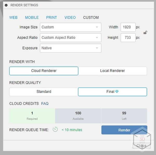
Key features include the program not only supporting cloud storage but also a cloud render, which can be accessed by users with slow computers for “credits” — a kind of internal software currency earned by active use of the program.
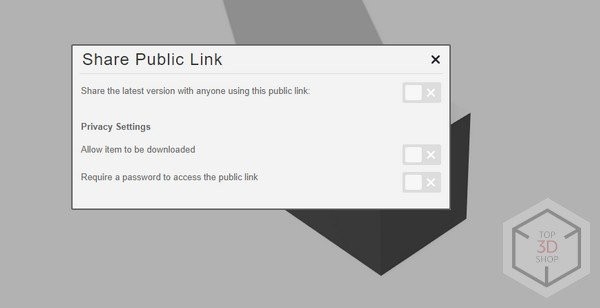
As already described above, group access is something that no software has ever offered. Publicly shared access to file settings, a separate file storage folder, file versions are just a part of what Fusion 360 has to offer to streamline project management.
Another feature of Fusion 360, no longer unique, is scripting. But these are not just the usual scripts we’re used to working with in Solidworks or Inventor, which utilize the model’s parametricity, assemblies and their parts as well as animation parameters. Autodesk introduced a dedicated section on their website, where anyone can download a template that will help speed up the design workflow.
Another noteworthy feature is that the program does not consume much computer resources and works using an online connection. The installation file is relatively small and takes up little hard drive memory, compared to other Autodesk programs, while installation usually takes about five minutes.
At first, Fusion 360 got a lot of backlash for its cloud-based limitations, with some users refusing to switch from Inventor to Fusion, fearing potential file leaks and that the program would not function offline. This issue is solved by engaging offline mode, when all changes and the file itself are saved on your local computer while the software continues to function with no Internet connection.
But you can’t stay offline all the time. An occasional web connection to upload files to the cloud, synchronize changes in the system and update the software is required, but with the current level of Internet coverage, this has become more easy.
Fusion 360 is a very versatile piece of software, capable of generating:
Fusion 360 seems like the all-in-one powerful solution capable of addressing the majority of CAD, CAM, CAE requirements. However, the list of available features depends on the type of the acquired license.
The basic Customer, or Hobbyist User license contains almost all of the functions, except for generative design, which was previously offered for a 30 day demo. As of 2022, these licenses have a limit on the number of files that can be shared for collaboration. All up-to-date details on the current license programs are available on the official Autodesk website. One of the most popular types of license is the educational version, which can be applied for by indicating your educational institution and attaching the relevant paperwork.
Creating a new design is done through the very top of the menu, on the left.
In addition to creating a model (New Design), you get the following options:
There are also standard Undo and Redo buttons (undo the action and redo the change). The timeline of actions is displayed at the bottom of the program window.

The history of actions has a start and rewind button, so many users mistakenly identify this as animation control, but in fact it displays the sequence of actions made in the file. Only 3D modeling transformations and everything that is not related to the sketch are showcased in the history. You can, however, rollback sketching actions, but they will not be displayed in the history.
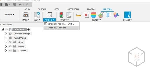
Tree view browsing is also available through the menu, a feature that no 3D program can do without.
Everything here is simple and concise, laid out in folders are “Bodies”, “Surfaces”, “Sketches”, “Origin” geometry, which can be moved around. You can create subfolders in the Bodies folder, combining them according to some setting, but, unfortunately, this is not possible in sketches. For orientation in sketches, you simply need to click on the body or object so that the sketch relating to the body is highlighted in the tree.
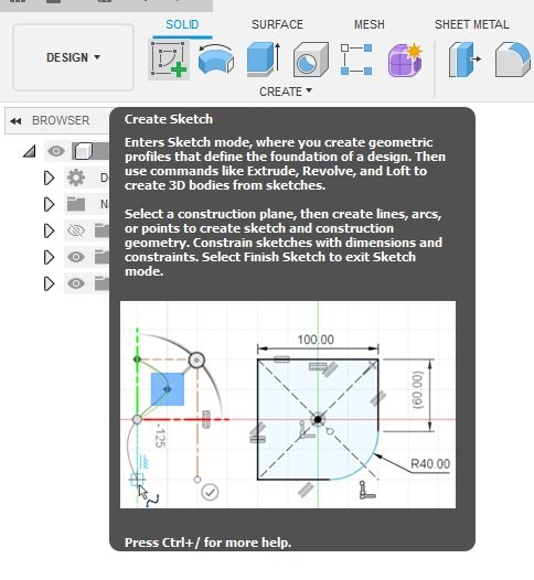
Let’s take a more detailed look at the design tools in the main menu. To create a sketch, go to the Solid tab and click on the Sketch button. When you point the cursor to each menu button, an interactive hint appears, which is very convenient for newly-fledged designers or those who have not used the software in a while.
An additional Sketch tab appears after clicking.
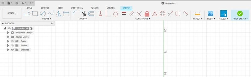
Further on, the procedures are quite intuitive. Command icons are self-explanatory, easy to navigate and will be familiar to those who come from an Inventor or Autocad background.
Sketches are created:
Main tools:
Especially worth noting is the inconspicuous item of creating a 3D sketch, which is usually highlighted in other programs as a separate button, or even a section.
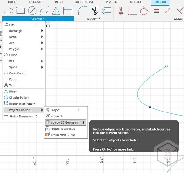
“Include 3D Geometry” is a tool that will add volume to a 2D sketch when converting into a 3D sketch, often utilized by advanced users to manipulate the trajectory or create surfaces by snapping to 3D objects. Many new users on the forums are asking if Fusion 360 can create and process 3D sketches, and the answer is definitely yes.
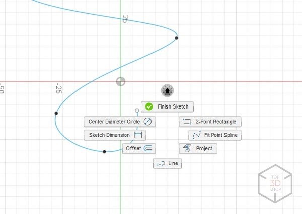
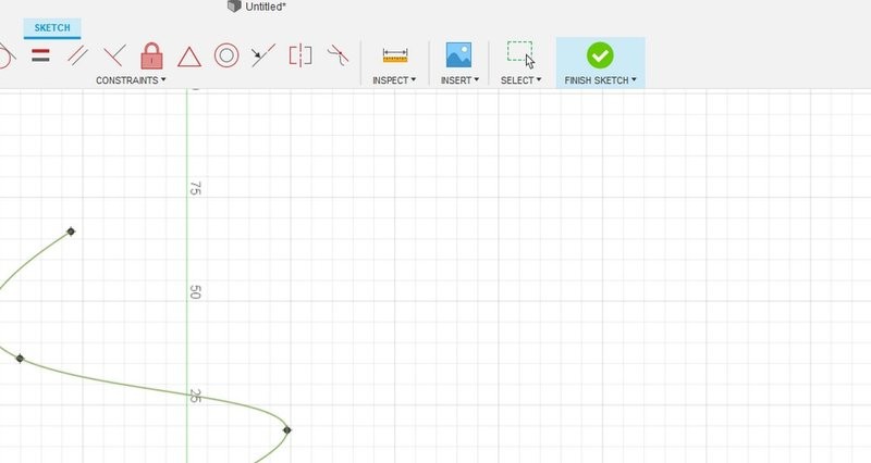
When the sketch is done, close it by clicking the right mouse button. After a context menu appears, click the checkmark or the big green checkmark in the top right of the menu window.
After finalizing the sketch, we need either the Solid menu or the Surface menu, depending on what kind of part we want to create.
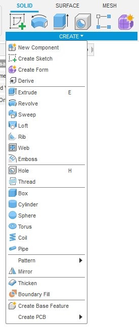
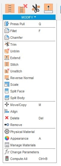
The Solid menu is divided according to functionality. On the left are model creation tools, with the models manipulation on the right. The most commonly used functions for creating a model are described below.
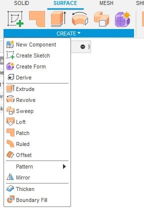
Almost all the tools in the Surface menu overlap with the ones in the Solid menu, with the exception that we are no longer manipulating solid bodies, but surfaces which obey the same laws of geometry as solid bodies. But the surface has no thickness, so instead of Thicken we see the Offset command, which copies the surface parallel to the selected one.
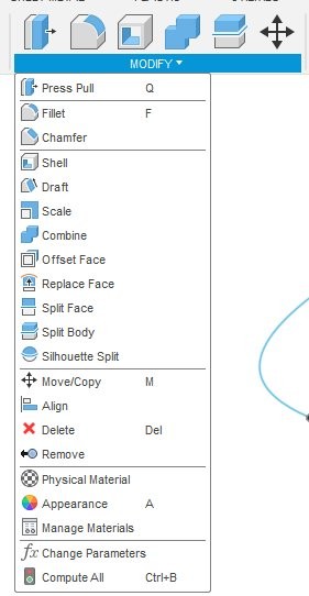
Changes to the solid component and in the surface are presented in the form of the already familiar Boolean operations and the addition of filets and chamfers by dividing the body into separate parts using plane cuts and moving individual parts of the body.
The procedure is almost the same for surfaces, only called differently.
Instead of the usual extrusion or Boolean difference, there is a surface Trim. The surface, as a complex object that does not have thickness, has normals, or a front surface, for simplicity. Which surface is the front or rear can be set by clicking Reverse normal.
Another noteworthy feature is the mode for creating a parametric form (Create form).
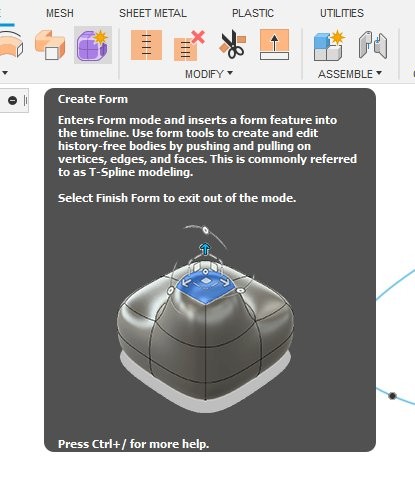
This is similar to polygonal modeling, but closer to T-Spline, that is, changing the model by revising parameters.
A very handy mode for modeling organic parts or surfaces that are not susceptible to conventional surface modeling.
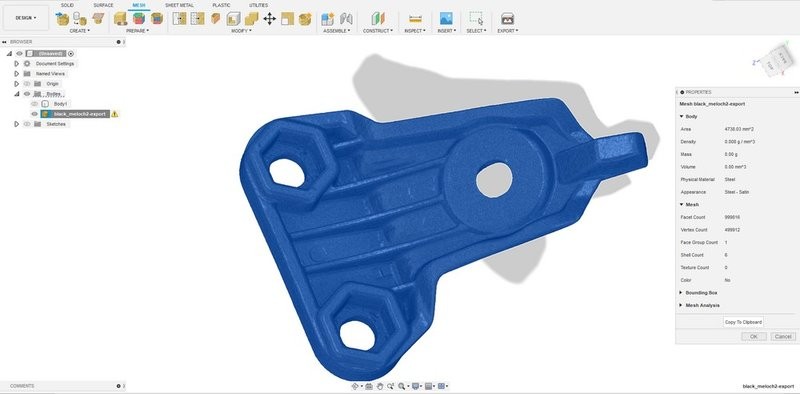
The next tab is responsible for managing the mesh (polygonal models), which has been increasingly sought after by engineers lately. Especially for professionals involved in 3D scanning which generates polygonal models and often requires conversion to a solid body. In part, Fusion 360 can be helpful here, but only for the simplest parts that allow you to plane cut and create a cross-section directly on the mesh. This is enough to convert the mesh into a workable solid body.
Some models comprising a large number of polygons can take a while to load, but a part with up to 1 million polygons is usually a quick load.
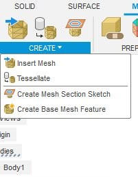
A little more about this menu.
The first button is responsible for inserting the mesh. Then, a command for creating a section needed to build a solid body appears in the pop-up menu.
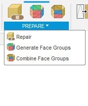
Next comes the tab responsible for splitting the mesh into separate sections. This method is used in more professional programs for reverse modeling. Repair is a handy tool for checking the model for inconsistency, voids and holes in the polygons. All corrupted surfaces will be fixed by clicking this button, creating a manifold object.
According to the self-explanatory logic, next come the mesh modification tools. These include such already familiar functions as Remesh, Plane Cut, and Reverse normals.
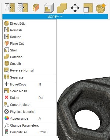
This is only a small part of the tools available for mesh processing. Unfortunately, it will take at least one more article to cover all of the functions just in this menu alone.
This tab is used for working with sheet metal.
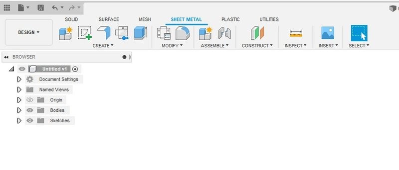
An intuitive section where you can create a production ready assembly from solid body sheets.
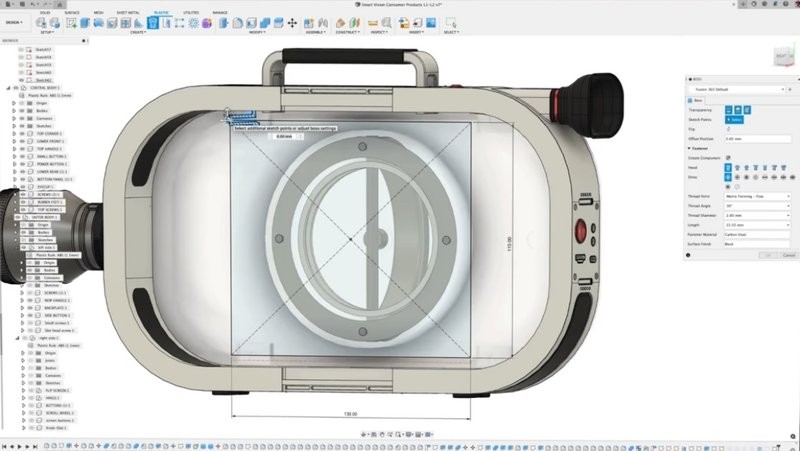
And the last menu on the list is called Plastic.

This tab also deserves a separate review effort, since it carries too many tools such as fittings for assembling objects from 3D printed parts, patterns for cooling vents, and a separate command for positioning fasteners.
A dedicated tab for analyzing the model's performance during casting.
In short, all of the features needed for analyzing casting and 3D printing are concentrated in this tab. These functions can be enabled in your personal Fusion 360 account.
If you feel like you lack some features in the variety of 3D modeling tools described above, then Fusion 360 Extensions are just what you are looking for. The extensions provide the user with even more advanced technologies and powerful toolsets allowing for the accomplishment of most complex tasks. All in all there are seven extensions offered by Autodesk, namely:
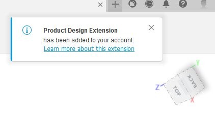
In terms of 3D modeling, the Product Design Extension is definitely worth a closer look.
The Product Design Extension is a set of advanced 3D modeling and design tools that allows for the simplified product development process and automated creation of complex product designs. You can use the intelligent patterns and add shape-altering properties to your 3D models. Manufacturing-aware guidance will help you choose the right solution for the best model performance and prepare your design for production.
What’s included?
You can use the Assign Plastic Rule and Manage Plastic Rule commands in the Design workspace, in the Plastic > Setup panel.
The Assign Plastic Rule command assigns a plastic rule to a component to automatically control the properties of plastic features, like physical material and thickness. You can expand each rule in the list to see its specific settings:
With the Manage Plastic Rules command you can create, edit, or save plastic rules in the active design.
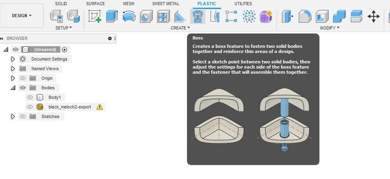
The new Boss and Snap Fit tools create plastic features.The Boss tool creates a boss feature to fasten two solid bodies together and reinforce thin areas of a design.
With the Snap Fit feature you are able to define a set of standard snap fits to use afterwards.
Presets allow you to reuse common values in a number of commands in Fusion 360, namely: Extrude, Rib, Web, Boss, Snap Fit, Emboss, Thicken, Shell, and Draft.
To create a Preset do the following:
Once the preset is created, you can apply, rename, edit, or delete it. Presets can not be saved in the cloud, but only locally.
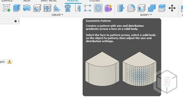
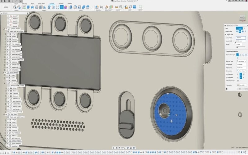
You can use the Geometric Pattern command to create a complex pattern with adjustable size and distribution gradients across a selected face on a solid body. The Geometric Pattern will be displayed on the selected faces on the solid body in the canvas
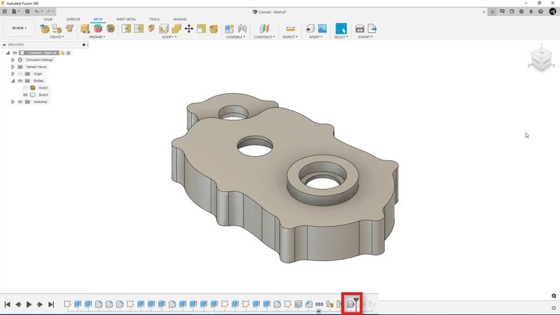
The Convert Mesh command allows you to convert a mesh body to a faceted or prismatic solid body or to an organic solid body.
In Product Design Extension you can transform some of the volumetric properties of a solid or closed mesh body to create complex volumetric lattices that alter the shape of your design. The Volumetric Lattice command adds an internal lattice structure within the boundary of a solid body.
To add a volumetric lattice, select a body, then select a cell shape and adjust its distribution, solidity, and offset settings.
To use the geometric results of a volumetric lattice, convert it to a mesh body. Right-click the body in the Browser and select Volumetric Lattice Actions > Create Mesh to convert the lattice to a mesh body.
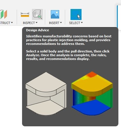
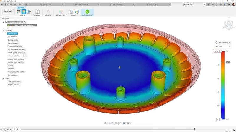
This feature provides manufacture-aware guidance based on best practices for plastic injection molding and company standards. You can get recommendations on how to improve the manufacturability and performance of your model.
Select a solid body and the pull direction, then click Analyze. As soon as the analysis is complete, in the Summary tab you can see summary cards for the alerts it found:
You will get the detailed recommendations on resolving the found alerts.
There are several options for installing Fusion 360. The main method is focused on a single user system, which simplifies the workflow and ensures that the Fusion 360 client is always up to date and supported by the software’s web services.
Some aspects of such workflow may not be feasible in managed environments where support is required for more PCs than those that have Fusion 360 installed. This document describes various installation alternatives if an organization needs to support more computing capacity:
Multi-user installation from web source.
Fusion 360 system requirements:
Imported formats include standard CAD files: .stp, .step, .iges, etc.
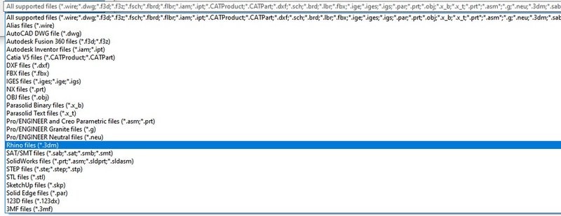
Fusion 360's native format utilizes the .f3d extension and stores all history and changes.
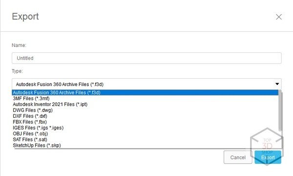
File export from Fusion 360 is possible in a large number of CAD-compatible formats.
Fusion 360 is a great piece of software that combines a lot of features to address CAD, CAM and CAE needs, from prototype to finished product.
We recommend Autodesk Fusion 360 for designing mechanical parts, critical assemblies, bodies and frames in mechanical engineering, auto, aircraft and many other areas wherever convenient and accurate design software is required.
Update your browser to view this website correctly. Update my browser now
Write a comment